Xtreme
Pag. 11
E l e c t r o n i c B r o a d c a s t E q u i p m e n t
Sec. 2 Positioning and initial pre-set of Xtreme II
Sec. 2-1 Xtreme’s best position
Xtreme II’s
best position is as close as possible to the transmitter, so that the stereo encoder output can be connected to
the transmitter via a route causing minimal variation to the wave shape of the MPX signal.
Xtreme II
outputs can pilot a coder with cable length of up to 3 m before any appreciable degradation of the MPX signal
is noted.
If this is impossible, the best solution is either to: power up an external coder located close to the transmitter energiser via
Xtreme’s
base band analogue output, or to use the digital output with an essentially flat frequency response plus a constant
wave train delay in the range 30 Hz to 15 KHz.
To ensure maximum transmission quality, all appliances downstream of the studio must be carefully aligned and must
satisfy the appropriate standards for wave width, distortion, wave train delay and gain stability.
These appliances must be re-checked at reasonable intervals.
It is therefore important that the sound source connected to
Xtreme II
has low noise at output, the flattest possible
frequency response and low distortion.
Sec. 2-2 At first power-up
Before powering up
Xtreme II,
make sure that mains power matches the value shown on the rear of the power supply and
that the electric system to which
Xtreme II
is connected, is supplied with a good grounding system.
The display may be difficult to understand at power-up, therefore, set the contrast level (see the appropriate section)
.
Sec. 3 Input/Output connections
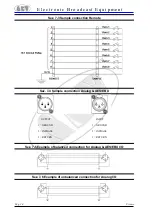
When connecting inputs/outputs, you are recommended to use a good quality, well shielded, soft cable.
Sec. 3-4 Remote control
Xtreme II
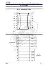
can be remotely controlled via an RS-232 standard serial port – this enables you to control it via both PC and
modem.
A 15-pole connector is also available on the
Xtreme II’s
rear side to send on air 8 different presets simply by means of a
command of an external switch. For connection details, see section “Connections” at the end of the manual
Preset assignments occur by means of “TLC” menu.


