20
S
COOPY
+ S - User Manual
2.3.
Audio interfaces and functions
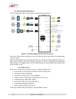
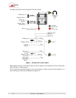
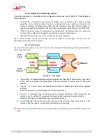
The following diagram shows the main audio processing and mixing functions:
Figure 2 – Functional diagram of the audio sub-system
The S
COOPY
+
S features two mixing buses, used for the left and right channels when the selected coding
is in stereo mode.
With the "HD-4G Mobile" option, a mobile voice link can be used for coordination when the coding is on
mono mode. In this case, the right "Program" mixing bus is used for coordination (as shown inside
square brackets in the diagram above).
The coordination cannot be used along with stereo audio coding
for the program channel.
2.3.1.
Mic/Line inputs
The S
COOPY
+
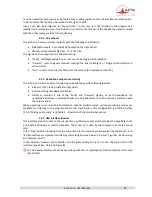
S includes three microphone inputs, each with following features:
Balanced input, 3-pin female XLR (located on the left and right sides)
48V phantom power (switchable)
Input sensitivity selector (0 / 16 / 32 / 48 dB gain)
20 dB attenuator for high level line signals (pad on input 3 only)
Switchable high-pass filter (50Hz, 18dB/o)
Mixer fader, using a front panel potentiometer
Switchable limiter (-8dBFS threshold).
Mute switch located on the front panel
All settings, except the fader potentiometer, are controllable by remote.
L im
H P F
O n /O ff
H P F
O n /O ff
H P F
O n /O ff
L im
L im
F a d e r
8 0 d B
F a d e r
8 0 d B
F a d e r
8 0 d B
M IC 1
P 4 8
O ff
M i c
p o w e r
M ic /L in e 1
P 4 8
O ff
P 4 8
O ff
M i c
p o w e r
M i c
p o w e r
P a d
2 0 d B
M ic /L in e 2
M ic /L in e 3
M IC 3
M IC 2
L in e R
L in e L
H e a d p h o n e 1
H e a d p h o n e 2
L in e L
L in e R
P G M (L ) b u s
P G M (L ) F B
P G M R
[ C o o r d in a ti o n ]
P G M R F B
[ C o o r d F B ]
U S B I n
P la y b a c k
R e c o r d
U S B
U S B
U S B O u t
P r o g ra m (L )
L e v e l
m e t e r in g
P r o g ra m R
[ C o o rd ]
M ix e r
S D
S D
Содержание Scoopy+ S
Страница 1: ...Mono stereo portable audio codec for real time transmission over ISDN POTS MOBILE IP User Manual ...
Страница 2: ......
Страница 135: ......


