pag.
28 di 64
Use and Maintenance Manual
M
MCCHH88--1111//EEM
M -- M
MCCHH1133--1166//EETT
Standard
Cap.4 _ Technical data
TECHNICAL CHARACTERISTICS
4 - TECHNICAL DATA
Crankcase, crankshaft, cylinders, pistons
4.1
4.1.1
Valves
4.1.2
Safety valves
4.1.3
Lubrication
4.1.5
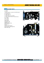
The crankcase is made of aluminium alloy; the flanges with roller bearings on the filter sides and ball bea-
rings on the fan side that support the crankshaft are kept oil-tight with the crankcase by O-rings between flan-
ge and crankcase and the oil retainer between flange and motor shaft.
The crankshaft and the connecting rods run on bearings with roller cages only. The connecting rods are
fitted on the crankshaft with a single crank angle.
The cylinders are made of cast iron, the pistons are made of aluminium and feature traditional multiple piston
rings. The high pressure stage piston has a special anti-wear lining. The relative cylinder is self-lubricating.
The heads set features outlet and intake valves. The 1
st
stage head is reed valve type and includes both
intake and pressure. The intake and pressure valves are inserted directly in the respective threaded seats of
the 2 nd and 3 rd stage heads. (Pressure valve of 3
rd
stage have no threads).
Splash lubrication occurs by oil thrower pins screwed onto the 2 nd and 3 rd stage connecting rods. Third
stage lubrication is of the oil vapour type.
Pressure maintenance valve
4.1.4
This valve is fitted after the final filter. When the compressor is switched on it keeps internal system
pressure at 100 ±20 bar so as to remove as much water as possible from the air.
Cooling tubes
4.1.6
The compressor and motor (electric or internal combustion type) are mounted on a welded steel frame that
has been painted with epoxy resins. The frame consists of painted panelling with a handle for the purpose of
moving it. Stainless steel frame available on request.
Frame, guards
4.1.7
The cooling pipes are made of stainless steel.
The safety valves are pre-adjusted during assembly of the compressor and prevent it being damaged in the
event of a malfunction. The max pressure, as a function of the valve, as follows:
1
st
stage safety valve 8 bar - (114 PSI)
2
nd
stage safety valve 50 bar - (710 PSI)
3
rd
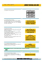
stage safety or final valve 225 bar - (3200 PSI)
300 bar - (4300 PSI)
330 bar - (4700 PSI)
WARNING
It is strictly forbidden to carry out any adjustments to the valve to raise its factory
preset pressure.
Tampering with the safety valve can cause serious damage and renders the warranty
null and void.


