Chapter 3: Electrical Specifications and Installation
DANGER
: To decrease the risk of electrical shock, injury, death, and damage to the
equipment, obey the precautions that follow.
l
Electrical installation must be done by qualified personnel.
l
Before you do maintenance to the equipment, disconnect the electrical power.
l
Before you connect wires to this product, disconnect the electrical power.
l
Make sure that all components are grounded correctly and that they obey the local
electrical safety requirements.
l
It is the responsibilty of the system integrator or qualified installer to determine and
meet all safety and compliance requirements when they integrate the AGV3D into a
completed system.
WARNING
: To prevent damage to the equipment and decrease the risk of electrical shock
and injury, obey the precautions that follow.
l
Only trained operators should operate this equipment.
l
Use this product only in environments and operating conditions that are approved
in this manual.
Electrical installation requirements will depend on the ordered product options. Installation instructions
in this section are for AGV3D stages equipped with standard Aerotech motors intended for use with an
Aerotech motion control system. Contact Aerotech for further information on products that are
otherwise configured.
Aerotech motion control systems are adjusted at the factory for optimum performance. When the
AGV3D is part of a complete Aerotech motion control system, setup should only require that you
connect the AGV3D to the appropriate drive chassis with the cables provided. Labels on the system
components should indicate the appropriate connections.
If system level integration was purchased, an electrical drawing that shows the system interconnects has
been supplied with the system (separate from this documentation).
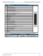
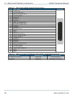
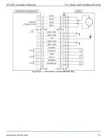
The electrical wiring from the motor and encoder are integrated at the factory. Refer to the sections that
follow for standard motor wiring and connector pinouts.
AGV3D Hardware Manual
Chapter 3: Electrical Specifications and Installation
www.aerotech.com
45
Содержание AGV3D Series
Страница 1: ...Revision 2 00 AGV3D Three Axis Laser Scan Head HARDWARE MANUAL...
Страница 6: ...This page intentionally left blank List of Tables AGV3D Hardware Manual 6 www aerotech com...
Страница 12: ...This page intentionally left blank Laser Shutter AGV3D Hardware Manual 12 www aerotech com...
Страница 14: ...This page intentionally left blank EU Declaration of Incorporation AGV3D Hardware Manual 14 www aerotech com...
Страница 16: ...Figure 1 2 Standard AGV3D Chapter 1 Overview AGV3D Hardware Manual 16 www aerotech com...
Страница 28: ...This page intentionally left blank 1 4 Software Configuration AGV3D Hardware Manual 28 www aerotech com...
Страница 32: ...Figure 2 2 AGV3D 30 Scan Head Dimensions 2 2 Dimensions AGV3D Hardware Manual 32 www aerotech com...
Страница 60: ...This page intentionally left blank Appendix B Revision History AGV3D Hardware Manual 60 www aerotech com...


