background image

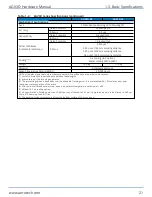
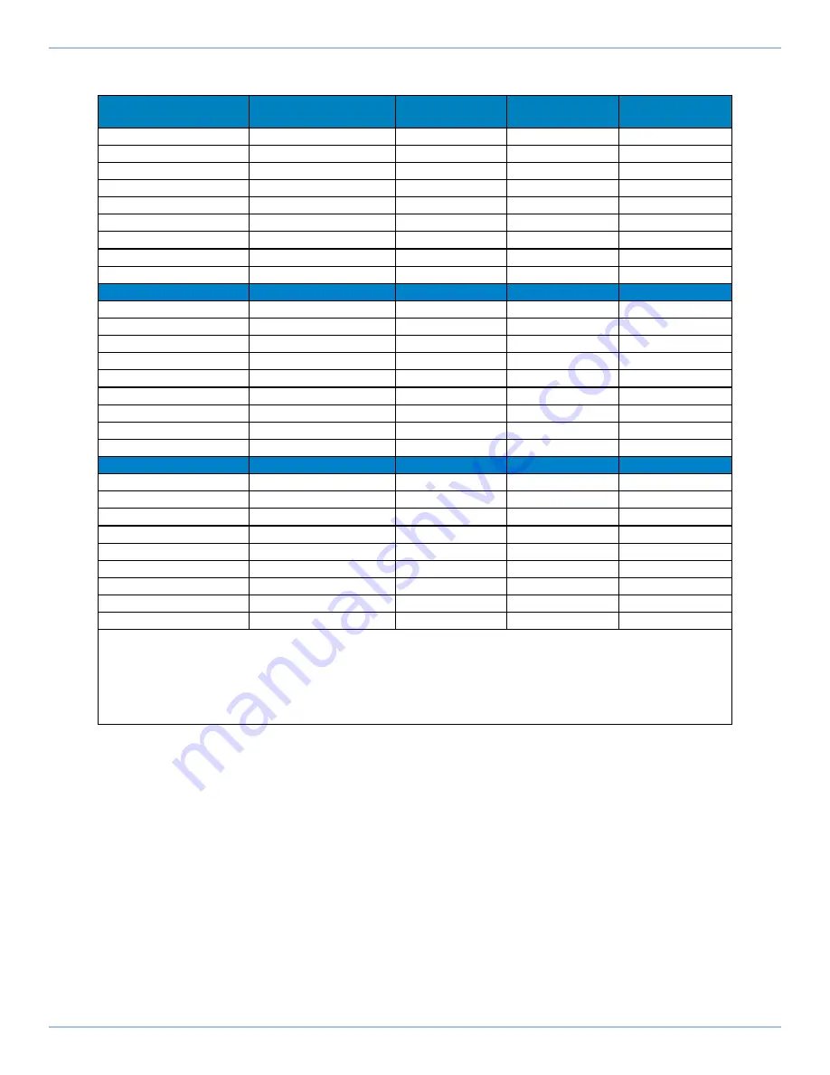
Table 1-6:

AGV3D-30 Spot Diameter Range (µm) within Field of View per Wavelength

Nominal Field of View

Nominal Working

Distance

343 nm

355 nm

515 nm

100 mm x 100 mm

83 mm

4.8 - 5.0

5.0 - 5.2

7.4 - 7.7

200 mm x 200 mm

221 mm

7.9 - 8.6

8.2 - 8.9

11.9 - 13.2

300 mm x 300 mm

358 mm

11.0 - 12.2

11.3 - 12.5

17.3 - 19.2

400 mm x 400 mm

495 mm

14.2 - 15.8

14.6 - 16.2

22.7 - 25.3

500 mm x 500 mm

632 mm

17.5 - 19.4

17.8 - 19.8

28.2 - 31.6

600 mm x 600 mm

770 mm

20.7 - 23.0

21 - 23.4

33.8 - 38.1

700 mm x 700 mm

907 mm

23.9 - 26.6

24.3 - 27

39.7 - 44.8

800 mm x 800 mm

1045 mm

27.0 - 30.1

27.5 - 30.6

45.7 - 51.8

1000 mm x 1000 mm

1320 mm

33.3 - 37.1

33.9 - 37.8

58.4 - 66.7

532 nm

1030 nm

1064 nm

100 mm x 100 mm

83 mm

7.7 - 7.9

14.6 - 14.7

15.0 - 15.2

200 mm x 200 mm

221 mm

12.2 - 13.6

22.4 - 24.7

23.3 - 25.7

300 mm x 300 mm

358 mm

17.8 - 19.8

32.3 - 35.9

33.4 - 37.0

400 mm x 400 mm

495 mm

23.3 - 26.0

42.2 - 47.1

43.5 - 48.5

500 mm x 500 mm

632 mm

28.9 - 32.4

52.2 - 58.4

53.8 - 60.1

600 mm x 600 mm

770 mm

34.6 - 38.9

62.3 - 69.8

64.1 - 71.7

700 mm x 700 mm

907 mm

40.5 - 45.6

72.6 - 81.4

74.5 - 83.5

800 mm x 800 mm

1045 mm

46.5 - 52.

82.8 - 93.0

84.9 - 95.3

1000 mm x 1000 mm

1320 mm

59.0 - 67.0

103.1 - 116.5

106.0 - 119.1

1550 nm

9.3 µm

10.6 µm

100 mm x 100 mm

83 mm

21.1 - 21.8

128.5 - 137.1

145.8 - 155.8

200 mm x 200 mm

221 mm

33.2 - 36.5

211.1 - 231.2

240.3 - 263.1

300 mm x 300 mm

358 mm

47.3 - 52.4

296.1 - 326.8

337.0 - 371.9

400 mm x 400 mm

495 mm

61.5 - 68.4

381.3 - 422.

433.9 - 481.0

500 mm x 500 mm

632 mm

75.8 - 84.5

466.5 - 518.6

531.0 - 590.3

600 mm x 600 mm

770 mm

90.1 - 100.7

552.0 - 614.9

628.3 - 699.9

700 mm x 700 mm

907 mm

104.5 - 116.0

637.6 - 711.4

725.8 - 809.8

800 mm x 800 mm

1045 mm

119.0 - 133.2

723.5 - 808.2

823.6 - 920.0

1000 mm x 1000 mm

1320 mm

148.0 - 166.0

895.9 - 1002.6

1019.9 - 1141.4

NOTES: 

l

Spot diameter is expressed as 1/e

2

assuming a beam quality of M

2

= 1.

l

The working distance is measured from the bottom surface of the scan head.

l

Refer to

Table 1-7

to determine which field configuration option is required to achieve a specific nominal field of

view for the desired wavelength.

l

Contact Aerotech for additional data.

AGV3D Hardware Manual

1.3. Basic Specifications

www.aerotech.com

23

Содержание AGV3D Series

Страница 1: ...Revision 2 00 AGV3D Three Axis Laser Scan Head HARDWARE MANUAL...

Страница 2: ...spare or replacement parts To get help immediately contact a service office or your sales representative Include your customer order number in your email or have it available before you call This man...

Страница 3: ...sions 31 2 3 Remove the Shipping Clamp 33 2 4 Securing the Scan Head to the Mounting Surface 35 2 5 Laser Beam Alignment 37 2 6 Air Requirements 40 2 7 Water Requirements 41 2 8 Changing the Dynamic F...

Страница 4: ...Figure 2 2 AGV3D 30 Scan Head Dimensions 32 Figure 2 3 Top Cover Removal 33 Figure 2 4 Shipping Clamp Detail 34 Figure 2 5 Mounting Point Locations 36 Figure 2 6 Alignment Fixture 37 Figure 2 7 Air C...

Страница 5: ...Specifications 36 Table 2 2 Mounting Specifications 36 Table 2 3 Recommended Beam Power Settings 38 Table 3 1 Motor and Feedback Connecter Pinouts X and Y Axis 47 Table 3 2 Mating Connector Part Numbe...

Страница 6: ...This page intentionally left blank List of Tables AGV3D Hardware Manual 6 www aerotech com...

Страница 7: ...obey the precautions that follow l Electrical installation must be done by qualified personnel l Before you do maintenance to the equipment disconnect the electrical power l Before you connect wires t...

Страница 8: ...al shock and injury obey the precautions that follow l Only trained operators should operate this equipment l Use this product only in environments and operating conditions that are approved in this m...

Страница 9: ...location where laser radiation is emitted Brief descriptions of each of the various radiation classes are presented in the table below Note that in addition to the dangers of radiation lasers can pose...

Страница 10: ...th a laser device that can generate a sufficiently intense beam a laser area will be produced that includes the aiming volume as well as the reflections from all objects that can be exposed to the rad...

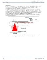
Страница 11: ...appropriate shutter as per any and all applicable regulations in order to prevent unwanted emission of the laser beam Place the beam shutter between the laser source and the scan head refer to Figure...

Страница 12: ...This page intentionally left blank Laser Shutter AGV3D Hardware Manual 12 www aerotech com...

Страница 13: ...rvice until the machinery into which it is to be incorporated or of which it is to be a component has been found and declared to be in conformity with the provisions of the Directive 2006 42 EC and wi...

Страница 14: ...This page intentionally left blank EU Declaration of Incorporation AGV3D Hardware Manual 14 www aerotech com...

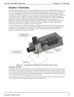
Страница 15: ...iginal size The scan head enclosure is fully sealed featuring cover glass and gaskets over both the input and exit apertures to make sure that no dust or particles can infiltrate the enclosure and cau...

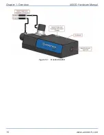
Страница 16: ...Figure 1 2 Standard AGV3D Chapter 1 Overview AGV3D Hardware Manual 16 www aerotech com...

Страница 17: ...ion 2 7 WC Water cooling Plate Optional MP1 Rear Mounting Plate MP2 Bottom Mounting Plate Integration Required TAS Integration Test as system Testing integration and documentation of a group of compon...

Страница 18: ...to 2 000 m 0 ft to 6 562 ft above sea level Contact Aerotech if your specific application involves use above 2 000 m or below sea level Vibration Use the system in a low vibration environment Excessiv...

Страница 19: ...for a minimum of four hours prior to performing any critical operations with the AGV3D Application of the feedback power supply can raise the temperature of the galvano motors resulting in a transient...

Страница 20: ...V 6 5 m s at 1000x1000 mm FOV 65 m s Z Focus 500 mm s 2 1 9 m s at 160 mm working distance 15 m s at 500 mm working distance 50 m s at 1000 mm working distance Stability Long Term Drift 4 Galvo Scanne...

Страница 21: ...000 hours NOTE All angles are optical unless otherwise noted All specifications are per axis unless noted 1 Contact Aerotech to inquire about additional wavelengths 2 As measured at the focusing appa...

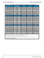
Страница 22: ...91 8 102 3 700 mm x 700 mm 907 mm 53 8 60 0 102 7 114 5 106 0 118 3 800 mm x 800 mm 1045 mm 61 0 68 1 116 5 130 1 120 3 134 3 1000 mm x 1000 mm 1320 mm 75 4 84 4 144 1 161 2 148 8 166 4 1550 nm 9 3 m...

Страница 23: ...69 8 64 1 71 7 700 mm x 700 mm 907 mm 40 5 45 6 72 6 81 4 74 5 83 5 800 mm x 800 mm 1045 mm 46 5 52 82 8 93 0 84 9 95 3 1000 mm x 1000 mm 1320 mm 59 0 67 0 103 1 116 5 106 0 119 1 1550 nm 9 3 m 10 6...

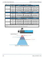
Страница 24: ...m 461 mm WD 375 mm x 375 mm 461 mm WD F2 Min 175 mm x 175 mm 186 mm WD Max 1000 mm x 1000 mm 1320 mm WD 1 1550 nm 9 3 m 10 6 m F1 Min 100 mm x 100 mm 83 mm WD Max 350 mm x 350 mm 427 mm WD 325 mm x 32...

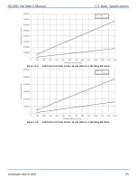
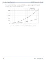
Страница 25: ...gure 1 4 AGV3D 20 X Y Axis Linear Acceleration vs Working Distance Figure 1 5 AGV3D 30 X Y Axis Linear Acceleration vs Working Distance AGV3D Hardware Manual 1 3 Basic Specifications www aerotech com...

Страница 26: ...alues are generally representative of system performance for all wavelength options If precise values for an alternate wavelength are required contact the factory Figure 1 6 AGV3D Z Axis Linear Accele...

Страница 27: ...iguration Refer to the AGV3D User Guide to configure the motion software Any PC included with the system from the factory will already be configured AGV3D Hardware Manual 1 4 Software Configuration ww...

Страница 28: ...This page intentionally left blank 1 4 Software Configuration AGV3D Hardware Manual 28 www aerotech com...

Страница 29: ...act Aerotech Global Technical Support DANGER Use of this product increases the risk of exposure to visible and or invisible laser radiation l Do not stare into the laser beam put your body parts in th...

Страница 30: ...d to its mounting surface to protect the optics IMPORTANT Wear clean powder free gloves when you handle optical components Carefully remove the AGV3D from its protective shipping container Gently set...

Страница 31: ...2 2 Dimensions Figure 2 1 AGV3D 20 Scan Head Dimensions AGV3D Hardware Manual 2 2 Dimensions www aerotech com 31...

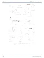
Страница 32: ...Figure 2 2 AGV3D 30 Scan Head Dimensions 2 2 Dimensions AGV3D Hardware Manual 32 www aerotech com...

Страница 33: ...er Removal 2 Carefully lift up the top cover from the front to access the shipping clamp NOTE The top cover can not be completely removed because there are cables attached to the underside of it WARNI...

Страница 34: ...you reattach the cover NOTE The top cover should be flush with the enclosure Carefully move any cables that interfere with the position of the top cover 6 Attach the top cover with the four QTY 4 M3 s...

Страница 35: ...ed residue and clean if necessary Use precision flatstones on the mounting surface to remove any burrs or high spots Clean the mounting surface with a lint free cloth and acetone or isopropyl alcohol...

Страница 36: ...Size Right Side 4 M6x1 9 mm LG Rear Side 4 M6x1 9 mm LG Bottom 4 M6x1 9 mm LG Table 2 2 Mounting Specifications Specification Parallelism to Workpiece 50 m over 100 mm Mounting Surface Flatness 25 m o...

Страница 37: ...laser safety precautions l Do not stare into the laser beam put your body parts in the laser area or expose yourself to reflections from powerful beams l Wear certified laser safety eye protection l...

Страница 38: ...hat was supplied with the laser 4 Adjust the position of the laser source until the beam is concentric with the marked circles on the front target of the alignment fixture 5 If the beam hits the rear...

Страница 39: ...ew sheet of paper for each test until the laser beam is correctly centered on the target 5 Remove the front target from the alignment fixture 6 Determine if the beam is aligned with the pinhole on the...

Страница 40: ...kPa to 586 kPa 75 psi to 85 psi is required Gas must be delivered via a polyurethane air hose with an outer diameter of 4 mm Unless otherwise specified a gas flow rate of 20 SLPM standard liters per...

Страница 41: ...le rubber If distilled water cannot be used contact the factory to discuss the specifics of your application If the WC water cooling option was purchased use this option to cool the galvo motors and t...

Страница 42: ...rt this procedure 1 Loosen but do not remove the four QTY 4 M4x0 7 14 mm LG socket head cap screws that are located in the slots on the bottom side of the AGV3D enclosure Figure 2 9 Dynamic Focusing M...

Страница 43: ...tighten the M4 socket head cap screws that were loosened in Step 2 l Alternate between the screws l Tighten the screws to a torque of 30 in lb 6 Use the AGV3D setup programs to update the parameter se...

Страница 44: ...clean powder free gloves when you handle optical components The user is responsible for supplying both the F Theta lens and a lens adapter Contact the factory for assistance 2 9 Using an F Theta Lens...

Страница 45: ...g conditions that are approved in this manual Electrical installation requirements will depend on the ordered product options Installation instructions in this section are for AGV3D stages equipped wi...

Страница 46: ...factory completely wired and assembled The X and Y axis galvo motors produce dual analog encoder feedback signals The Z axis motor produces single analog encoder feedback signals The Primary X Y and Z...

Страница 47: ...Motor 14 SIN1 Encoder Sine 1 15 COS1 Encoder Cosine 1 16 5V Common Ground 17 SIN2 Encoder Sine 2 18 COS2 Encoder Cosine 2 19 CCW LMT The limit signal that shows the maximum permitted machine travel in...

Страница 48: ...tor 14 SIN Encoder Sine 15 COS Encoder Cosine 16 Common ground 17 Reserved 18 Reserved 19 Reserved 20 MRK Encoder Marker 21 Common ground 22 Common ground 23 Signal Shield Connection 24 Motor 25 Motor...

Страница 49: ...access to the AGV3D when it is connected to a power source AGV3D scan heads are wired and assembled at the factory Contact your Aerotech representative if you have any questions on system configuratio...

Страница 50: ...Figure 3 2 X and Y Axis Motor and Feedback Wiring 3 2 Motor and Feedback Wiring AGV3D Hardware Manual 50 www aerotech com...

Страница 51: ...Figure 3 3 Z Axis Motor and Feedback Wiring AGV3D Hardware Manual 3 2 Motor and Feedback Wiring www aerotech com 51...

Страница 52: ...4 Inductance 170 H 1 12 mH Maximum Bus Voltage 80 V 80 V Number of Poles 2 N A Table 3 7 AGV3D 30 Motor and Feedback Specifications Feedback Specifications X and Y Motors Z Motor Supply Voltage 5 V Su...

Страница 53: ...manual The internal optical components are precisely aligned at the factory in a clean environment to achieve high performance Removal of any components will significantly compromise performance and...

Страница 54: ...atively soft substances and incorrect cleaning techniques will result in surface damage and drastically reduced component lifetime The cleaning procedure for the AGV3D is intended to help prolong the...

Страница 55: ...G PROCEDURE 1 Remove the four QTY 4 M6x1 0 16 mm LG socket head cap screws that secure the exit aper ture protective window mounting bracket 2 Remove the mounting bracket protective window and o ring...

Страница 56: ...for tuning instructions Encoder signals not optimized Refer to the controller documentation for encoder tuning instructions Reduction in power as the laser beam passes through the scan head Optical su...

Страница 57: ...zation RMA number must accompany any returned product s The RMA number may be obtained by calling an Aerotech service center or by submitting the appropriate request available on our website www aerot...

Страница 58: ...al rates apply If during the on site repair it is determined the problem is not warranty related then the terms and conditions stated in the following On Site Non Warranty Repair section apply On site...

Страница 59: ...Appendix B Revision History Revision Description 2 00 General update 1 01 Updated Section 1 3 Basic Specifications 1 00 New Manual AGV3D Hardware Manual Appendix B Revision History www aerotech com 59...

Страница 60: ...This page intentionally left blank Appendix B Revision History AGV3D Hardware Manual 60 www aerotech com...

Страница 61: ...tion 45 EN 60204 1 2010 13 EN ISO 12100 2010 13 EU 2015 863 13 F Feedback Specifications 52 field service 53 H Handling the Scan Head 30 Humidity 18 I Inspection 53 54 Inspection Schedule 53 isopropyl...

Страница 62: ...age 30 stage stabilizing 30 T Table of Contents 3 Temperature Effects 19 Tuning 46 Turning Mirrors 55 U Unpacking and Handling the Scan Head 30 V Vibration 18 W Warranty and Field Service 57 Water Req...

Отзывы: