background image

CHT-100 Cylinder Head Temperature Indicator 

Page 7 of 11


Aerospace Logic Inc. 

3150 Ridgeway Drive, Unit #43, Mississauga, Ontario, L5L 5R5, CANADA 

Tel. (905) 569-3887 | Fax. (416) 352-5854 | Email. [email protected] 

www.aerospacelogic.com 

CHT-100 Operations & Installation Manual – Ver. 1.9 – June 5, 2003
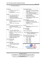


L

 (Low Temperature Limit Set) 

 
The low temperature limit should be set to the manufacturers recommended low 
limit for correct operation. This setting determines the point at which the bar 
indicator will begin to turn on. Values for this setting can range from 200ºF to 
400ºF. 
 
Moving the 

A M S

 switch to the 

A

 position and holding it there will allow the 

temperature to increment. Initially the increment will be at a slow rate and then 
speed up to a faster rate for easy selection. Once the increment is in the fast 
mode it can be slowed again by moving the 

A M S

 switch once to the 

M

 position 

and then back to the 

A

 position. Once the maximum (400ºF) has been reached 

the count will start over at 200ºF. 
  
Once the correct temperature has been reached, by moving between the 

A

 and 

M

 positions of the 

A M S

 switch, move the 

A M S

 switch once to the 

S

 position 

and release. The low limit will now be saved and applied to all cylinders. The 
display will move to the next parameter. 


H

 (High Temperature Limit Set) 

 
The high temperature limit should be set to the manufacturers recommended 
high limit for correct operation. This setting determines the point at which all bars 
on the bar indicator will turn on.  Values for this setting can range from the low 
limit plus 20ºF to 700ºF. 
 
Moving the 

A M S

 switch to the 

A

 position and holding it there will allow the 

temperature to increment. Initially the increment will be at a slow rate and then 
speed up to a faster rate for easy selection. Once the increment is in the fast 
mode it can be slowed again by moving the 

A M S

 switch once to the 

M

 position 

and then back to the 

A

 position. Once the maximum (700ºF) has been reached 

the count will start over at the preset low limit plus 20ºF. 
  
Once the correct temperature has been reached, by moving between the 

A

 and 

M

 positions of the 

A M S

 switch, move the 

A M S

 switch once to the 

S

 position 

and release. The high limit will now be saved and applied to all cylinders.  


DonE


The display will now show the characters 

DonE

 and the instrument will restart. At 

this point you have completed all the setup and configuration of the instrument 
and it is ready for service. 


Содержание CHT-100

Страница 1: ...0 Cylinder Head Temperature Indicator This instrument is a complex precision instrument manufactured to exceed Airborne Equipment Standards DO 160D DO 178B and TSO C43c standards In order for your ins...

Страница 2: ...o ensure that it is functioning correctly In turn the main processor validates the independent monitoring processor Any failure detected in either processor and your instrument display will be shut do...

Страница 3: ...sure proper operation The instrument has been software calibrated and never needs recalibration provided no wiring modifications are made at installation time Now connect the supply and dimmer wiring...

Страница 4: ...r 4 RED Cylinder 2 GREEN Cylinder 5 WHITE Cylinder 3 YELLOW Cylinder 6 If you have purchased a complete instrument and probe kit appropriate connectors for interconnection of the signal wires and prob...

Страница 5: ...Page 5 of 11 Aerospace Logic Inc 3150 Ridgeway Drive Unit 43 Mississauga Ontario L5L 5R5 CANADA Tel 905 569 3887 Fax 416 352 5854 Email sales aerospacelogic com www aerospacelogic com CHT 100 Operati...

Страница 6: ...n the setup mode the display bar will remain blank The CYL digit and the four digit display shows the parameter value and type as per the enclosed instructions In order to set the manufacturer specifi...

Страница 7: ...tch once to the S position and release The low limit will now be saved and applied to all cylinders The display will move to the next parameter H High Temperature Limit Set The high temperature limit...

Страница 8: ...isplay the STEP message for approximately five seconds before starting the step process Once started it will step through all cylinders When the last is reached it will revert back to the first 1 Disp...

Страница 9: ...his mode of operation is the single most important feature of this instrument and should be used for all leaning and cooling function If the instrument is switched from the automatic mode back to the...

Страница 10: ...mocouple Signal Wire Junction Where possible plan the installation such that the junction between the thermocouple and signal wire takes place on the cockpit side of the firewall If this is not possib...

Страница 11: ...sation for thermocouple sensor linearity Minimum 256 times measurement validation before display Operating Temperature 15C to 55C 5F to 131F Power Consumption 370mA Max daytime operation 50mA Min nigh...

Отзывы: