CHT-100 Cylinder Head Temperature Indicator
Page 10 of 11
Aerospace Logic Inc.
3150 Ridgeway Drive, Unit #43, Mississauga, Ontario, L5L 5R5, CANADA
Tel. (905) 569-3887 | Fax. (416) 352-5854 | Email. [email protected]
www.aerospacelogic.com
CHT-100 Operations & Installation Manual – Ver. 1.9 – June 5, 2003
6. Probe
Installation
NOTE:
This section refers primarily to installation of probes supplied as a kit
with the specific instrument. For installation using existing or owner supplied
probes please see the specific probe manufacturer information.
The instrument will support all grounded and ungrounded probes that meet
the requirements listed in the Specification Section.
Thermocouple / Signal Wire Junction
Where possible, plan the installation such that the junction between the
thermocouple and signal wire takes place on the cockpit side of the firewall. If
this is not possible ensure that the junction is in the coolest possible location
in the engine compartment.
Ensure that ALL thermocouple leads are strapped together at the junction
point. This will further eliminate the possibility of any ground loop problems.
Connection
Thermocouple leads are marked with red (negative) and white (positive)
sleeves and match the corresponding red and white twisted pair signal wires.
Simply snap the corresponding connections together, slide the heat shrink
sleeve over the junction and shrink to size when installing the instrument.
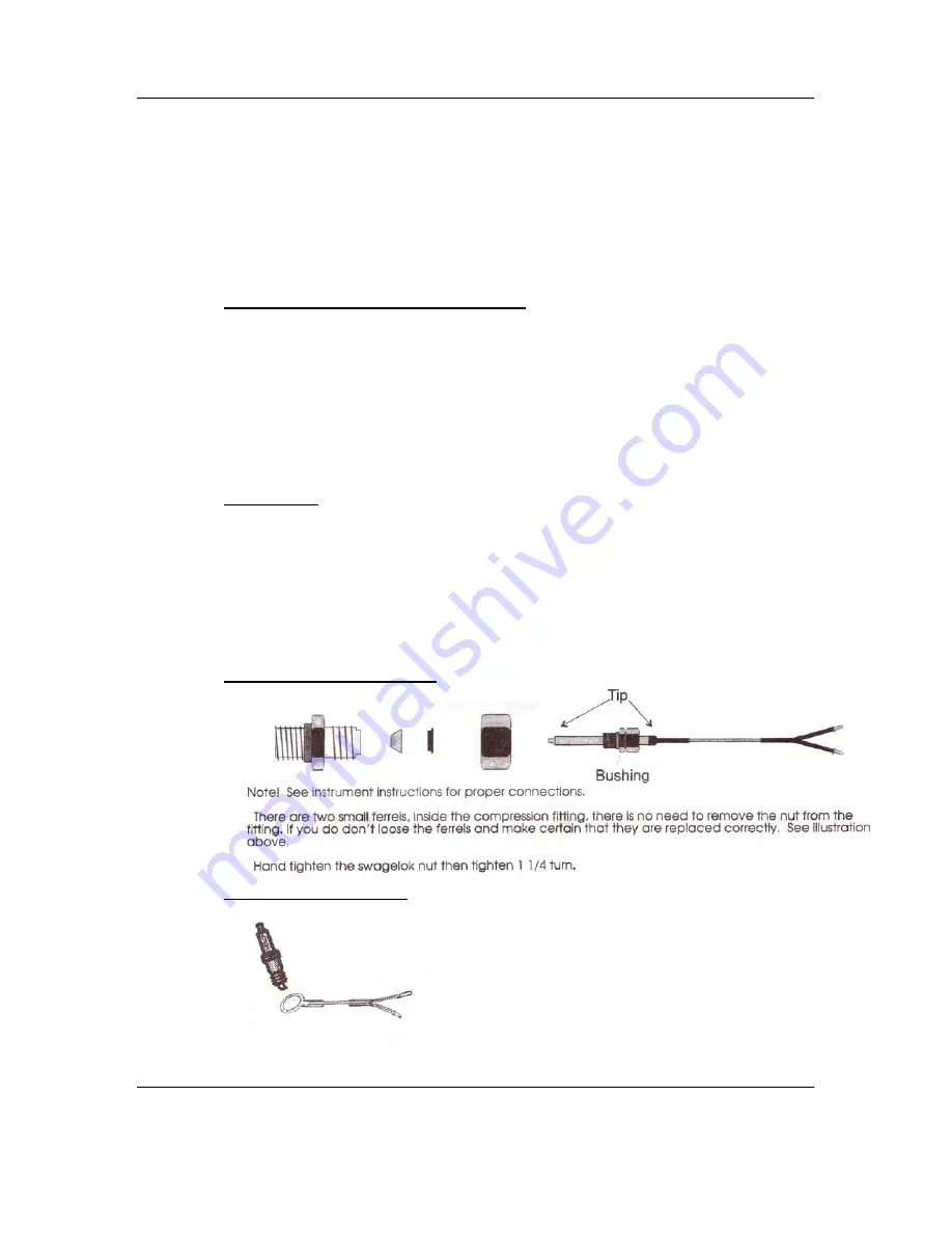
For installation of the thermocouple probe see the illustrations below:
For Bayonet Type Probes:
For Ring Type Probes:

