INRP260HzTY. 1312. 5806717_03
MULTIPURPOSE UNITS FOR 2/4 - PIPE SYSTEMS - Technical manual
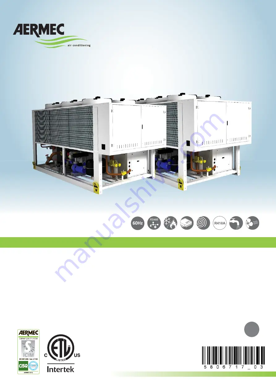
NRP 0800-1800
REVERSIBLE HEAT PUMPS
• DESIGNED FOR 2 AND 4 PIPE SYSTEMS FOR
EXTERNAL INSTALLATION
• OUTDOOR
UNIT
• HIGH
EFFICIENCIES
EN
Страница 1: ...0HzTY 1312 5806717_03 MULTIPURPOSE UNITS FOR 2 4 PIPE SYSTEMS Technical manual NRP 0800 1800 REVERSIBLE HEAT PUMPS DESIGNED FOR 2 AND 4 PIPE SYSTEMS FOR EXTERNAL INSTALLATION OUTDOOR UNIT HIGH EFFICIENCIES EN ...
Страница 2: ...xperience and in depth engineering research and it is built using top quality materials and advanced technologies In addition the EC mark guarantees that our appliances fully comply with the requirements of the European Machinery Directive in terms of safety We constantly monitor the quality level of our products and as a result they are synonymous with Safety Quality and Reliability Product data ...
Страница 3: ...ctors for data different than nominal in cooling mode 19 11 1 Cooling capacity and input power 19 11 2 For t different from the rated value 19 11 3 Fouling factors 19 11 4 Hea ng capacity and input power 20 11 5 For t different from the rated value 20 11 6 Fouling factors 20 11 7 Correc ve coefficients of recovered hea ng capacity 21 11 8 For t different from the rated value 21 11 9 Fouling factors 21 1...
Страница 4: ...hey are always at hand in case of need Read this sheet carefully the execution of all works must be performed by qualified staff according to Standards in force on this subject in different countries Ministerial Decree 329 2004 1 2 INSTALLATION The unit must be installed in such a way that maintenance and or repairs can be carried out 1 3 WARRANTY The appliance warranty does not cover the costs fo...
Страница 5: ...er heat pump controlling condensation and evaporation on two distinct plate heat exchangers associated to circulation of cold and hot water in the system It automatically changes from one configuration to another managed by on board microprocessor to optimise the spent energy depending on the demand by the utility Maximum reliability Multi circuit unit designed to provide the maximum efficiency bo...
Страница 6: ...gnet circuit breakers 13 14 System side hydronc kit 00 Without hydronic kit P1 Single low head pump P2 Single low head pump and reserve pump P3 Single high head pump P4 Single high head pump and reserve pump 15 16 DHW side idronic kit 1 00 Without hydronic kit R1 Single low head pump R2 Single low head pump and reserve pump R3 Single high head pump R4 Single high head pump and reserve pump 1 DHW S...
Страница 7: ...xchanger CONDENSATION Heat exchange with air ĞƐĐƌŝƉƟŽn OperaƟŽŶ 1 SYSTEM SIDE heat exchanger CONDENSATION Hot water prŽĚƵĐƟŽŶ 2 DHW SIDE heat exchanger not running 3 SOURCE SIDE heat exchanger EVAPORATION Heat exchange with air H2 O SYSTEM RETURN H2 O SYSTEM RETURN H2 O SYSTEM FLOW H2 O SYSTEM FLOW 1 2 3 3 1 2 3 3 2 Key 1 System side heat exchanger 2 DHW side heat exchanger 3 Source side heat exch...
Страница 8: ...hanger EVAPORATION Heat exchange with air ĞƐĐƌŝƉƟŽn OperaƟŽŶ 1 SYSTEM SIDE heat exchanger EVAPORATION Cold water prŽĚƵĐƟŽŶ 2 DHW SIDE heat ex changer CONDENSATION DHW prŽĚƵĐƟŽŶ 3 SOURCE SIDE heat exchanger Not running DHW SYSTEM H2 O DHW SYSTEM SUPPLY H2 O DHW SYSTEM H2 O DHW SYSTEM H2 O DHW SYSTEM SUP PLY H2 O DHW SYSTEM SUPPLY H2 O 1 2 3 3 1 2 3 3 Key 1 System side heat exchanger 2 DHW side heat...
Страница 9: ...2 O SYSTEM FLOW H2 O SYSTEM FLOW 1 1 3 3 3 3 ĞƐĐƌŝƉƟŽn OperaƟŽŶ 2 DHW SIDE heat exchanger CONDENSATION DHW prŽĚƵĐƟŽŶ 3 SOURCE SIDE heat exchanger EVAPORATION Heat exchange with air DHW SYSTEM H2 O DHW SYSTEM SUPPLY H2 O 2 2 ĞƐĐƌŝƉƟŽn OperaƟŽŶ 1 SYSTEM SIDE heat ex changer EVAPORATION Cold water prŽĚƵĐƟŽŶ 2 DHW SIDE heat exchanger not running 3 SOURCE SIDE heat ex changer CONDENSATION Heat exchange...
Страница 10: ...changer Not running DHW SYSTEM H2 O DHW SYSTEMH2 O DHW SYSTEM SUPPLY H2 O DHW SYSTEM SUPPLY H2 O 2 PIPE SYSTEM 1 1 3 3 3 3 2 2 Key 1 System side heat exchanger 2 DHW side heat exchanger 3 Source side heat exchanger AL Liquid storage tank CV One way valve F DehydratŽƌ Įůter IDL Liquid indicator HPT High pressure transducer HPS High pressure switch LPT Low pressure transducer LS Liquid separator TEV...
Страница 11: ...de from clogging FLOW SWITCHES They have the task of controlling that there is water circulation inside the heat exchangers if this is not the case they block the unit AIR VENT VALVE Mounted on the top of the hydraulic system they discharge possible air pockets 7 4 1 COMPONENTS OF HYDRAULIC CIRCUIT IN CONFIGURABLE VERSIONS PUMPS High or low static pressure EXPANSION VESSEL With nitrogen pre load m...
Страница 12: ...stallation of one or all the resistances is not foreseen 8 2 ELECTRIC ACCESSORIES AER485P1 RS 485 interface for supervising systems with MODBUS protocol AERWEB300 Accessory AERWEB allows remote control of a chiller through a common PC and an ethernet connection over a common browser 4 versions available AERWEB300 6 Web server to monitor and remote control max 6 units in RS485 network AERWEB300 18 ...
Страница 13: ...nput power A kW 70 91 79 71 87 11 111 92 126 32 140 72 149 92 158 92 Water flow rate A gpm 163 85 184 29 206 04 261 57 297 09 332 60 353 90 374 92 Pressure drops SYSTEM SIDE VERS 2 PIPES A PSI 16 37 13 89 13 69 10 67 12 95 7 43 13 42 11 61 Pressure drops DHW SIDE SYSTEM SIDE A PSI 33 26 30 37 29 62 24 82 29 56 22 62 35 70 33 91 ENERGY INDEX EER A BTU W 9 70 9 63 9 56 9 70 9 67 9 67 9 60 9 56 COP A...
Страница 14: ... SIDE A PSI 5 63 6 35 3 90 5 24 5 76 6 49 6 61 6 81 TOTAL RECOVERY MODE SYSTEM SIDE PUMP Available static pressure Low static pressure pump A PSI 22 8 21 7 21 5 20 9 25 7 22 7 23 3 22 2 Available static pressure High static pressure pump A PSI 40 2 39 0 38 7 37 5 44 9 41 3 45 3 44 3 TOTAL RECOVERY MODE DHW SYSTEM SIDE PUMP Available static pressure Low static pressure pump A PSI 23 4 20 4 19 8 20 ...
Страница 15: ...8 281 309 333 348 MOP A 192 207 218 295 342 370 393 394 Recommended fuse A 175 200 200 250 300 350 350 350 SYSTEM DHW SYSTEM HIGH HEAD PUMPS LRA A 312 363 373 468 522 550 581 576 MCA A 170 180 190 254 288 316 347 362 MOP A 199 214 224 301 348 376 408 409 Recommended fuse A 175 200 200 300 300 350 400 400 ELECTRICAL DATA 575V 3 60HZ POWER SUPPLY Input current cooling mode A 88 94 100 126 143 160 17...
Страница 16: ...2 31 2 Input current 575V A 18 7 18 7 18 7 25 0 25 0 25 0 25 0 25 0 SYSTEM SIDE HEAT EXCHANGER Quantity n 1 1 1 1 1 1 1 1 Water content dm 20 0 22 5 30 2 32 9 37 4 41 0 45 5 50 0 Water connections inch 3 3 3 4 4 4 4 4 SYSTEM SIDE 2 AND 4 PIPES HYDRONIC KIT EXPANSION VESSEL Quantity expansion vessel n 2 2 2 2 2 2 2 2 Content expansion vessel gal 25 25 25 25 25 25 25 25 Expansion vessel calibration ...
Страница 17: ...W 5 5 5 5 5 5 7 5 7 5 7 5 11 0 11 0 Input current 230V A 18 4 Input current 460V A 9 2 9 2 9 2 11 0 11 0 11 0 17 3 17 3 Input current 575V A 7 4 7 4 7 4 8 8 8 8 8 8 13 8 13 8 SOUND DATA COOLING MODE Sound power A dB 89 92 93 94 95 96 96 96 Sound pressure A dB 57 60 61 62 63 64 64 64 DIMENSIONS WEIGHT Height inch 96 5 96 5 96 5 96 5 96 5 96 5 96 5 96 5 Width inch 86 6 86 6 86 6 86 6 86 6 86 6 86 6 ...
Страница 18: ...7 80 90 100 110 120 130 140 CHILLER TOTAL RECOVERY PRODUCED WATER TEMPERATURE RECOVERY In summer mode the unit can be started with external air 46 C 114 8 F and inlet water 35 C 95 F In winter and RECOVERY mode the unit can be started with external air 15 C 5 F and inlet water 20 C 68 F In these conditions operation is only allowed for a short amount of time and to bring the system to the proper t...
Страница 19: ...erature between the input and output of the condenser equal to 5 C 10 F KEY Pc Cooling capacity Pa Input power Cf Cooling capacity correction coefficient Ca Input power correction coefficient 11 2 FOR ΔT DIFFERENT FROM THE RA TED VALUE For Δt different from 5K refer to Tab t DIFFERENT FROM NOMINAL t 5 for the cooling capacity and input power correction factors 11 3 FOULING FACTORS The performance ...
Страница 20: ...rrection factors 11 6 FOULING FACTORS The performance levels indicated in table FOUL ING FACTOR K M2 W refer to conditions with clean tubes with a fouling factor 1 For values different from the fouling factor multiply the values in the performance table by the reported coefficients t DIFFERENT FROM NOMINAL t 5 3 5 8 10 Heating capacity 0 99 1 1 01 1 02 Input power 1 01 1 0 98 0 96 0 7 0 8 0 9 1 0 ...
Страница 21: ...cient 0 8 0 9 1 0 1 1 1 2 1 3 1 4 42 44 46 48 50 52 54 56 58 60 62 41 64 4 5 6 7 8 9 10 11 12 13 14 15 16 17 18 C F E D C B A Ch HEATING CAPACITY RECOVERED POWER CORRECTION COEFFICIENT Ph HEATING CAPACITY TEMPERATURE OF THE WATER PRODUCED AT THE EVAPORATOR TEMPERATURE OF THE WATER PRODUCED AT RECOVERY A B C D E Condenser utput water temeprature C 35 40 45 50 55 F 95 104 113 122 131 A B C D E Conde...
Страница 22: ...800 2 0900 3 1000 4 1250 5 1400 6 1500 7 1650 8 1800 CORRECTIVE FACTORS TABLE EVAPORATOR Average water temperature C F 5 41 10 50 15 59 20 68 30 86 40 104 50 122 Multiplicative coefficients 1 02 1 00 0 98 0 97 0 95 0 93 0 91 Evaporator inlet water temperature 7 C 44 6 F Evaporator outlet water temperature 12 C 53 6 F External air temperature 35 C 95 F Average water temperature 10 C 50 F For temper...
Страница 23: ...00 A gpm 83 02 245 68 NRP 0900 A gpm 94 51 245 68 NRP 1000 A gpm 106 80 356 00 NRP 1250 A gpm 133 84 446 13 NRP 1400 A gpm 154 50 515 01 NRP 1500 A gpm 174 88 528 34 NRP 1650 A gpm 187 93 528 34 NRP 1800 A gpm 200 76 528 34 CORRECTIVE FACTORS TABLE EVAPORATOR Average water temperature C F 23 73 4 28 82 4 33 91 4 38 100 4 43 109 4 48 118 4 53 127 4 58 136 4 Multiplicative coefficients 1 04 1 03 1 0...
Страница 24: ...0 40 50 100 200 300 380 55 kPa PSI 1 2 3 4 5 Key NRP 1 0800 0900 2 1000 3 1250 4 1400 1500 1650 5 1800 88 188 288 388 488 528 20000 30000 40000 50000 60000 70000 80000 90000 100000 110000 120000 gpm l h 0 0 10 20 30 40 50 100 200 300 380 55 kPa PSI 1 2 3 4 5 13 1 LOW STATIC PRESSURE PUMPS IN COOLING MODE SYSTEM SIDE 13 2 HIGH STATIC PRESSURE PUMPS IN COOLING MODE SYSTEM SIDE 24 INRP260HzTY 1312 58...
Страница 25: ... 380 55 kPa PSI 1 2 3 4 5 Key NRP 1 0800 0900 2 1000 3 1250 1500 4 1650 1800 88 188 288 388 488 528 20000 30000 40000 50000 60000 70000 80000 90000 100000 110000 120000 gpm l h 0 0 10 20 30 40 50 100 200 300 380 55 kPa PSI 1 2 3 4 13 3 LOW STATIC PRESSURE PUMPS IN COOLING MODE RECOVERY MODE 13 4 HIGH STATIC PRESSURE PUMPS IN COOLING MODE RECOVERY MODE 25 INRP260HzTY 1312 5806717_03 ...
Страница 26: ...mum water content admitted the HOT SIDE gal ton 6 50 6 50 6 50 6 50 6 50 6 50 6 50 6 50 Recommended water content COOLING SIDE HEATING SIDE gal ton 13 01 13 01 13 01 13 01 13 01 13 01 13 01 13 01 14 EXPANSION VESSEL CALIBRATION 14 1 EXPANSION VESSEL CALIBRATION Standard pre load pressure value of the expansion vessel is 1 5bar 21 8PSI whereas volume is 24 litres Maximum pressure 6bar 87PSI Calibra...
Страница 27: ...t C F 0 32 5 23 7 19 4 10 14 13 8 6 15 5 20 4 25 13 30 22 37 34 6 44 47 2 Percent ethylene glycol 0 12 15 20 25 30 35 40 45 50 55 Qw 1 00 1 052 1 066 1 088 1 111 1 133 1 155 1 177 1 199 1 220 1 242 Pc 1 000 0 988 0 985 0 980 0 975 0 970 0 965 0 960 0 955 0 950 0 945 Pa 1 000 0 995 0 994 0 992 0 990 0 988 0 986 0 984 0 982 0 980 0 978 Dp 1 103 1 159 1 222 1 292 1 368 1 452 1 541 1 637 1 740 1 849 H...
Страница 28: ...7 3 88 5 86 4 80 0 67 1 1400 A 95 63 75 88 9 85 4 86 8 91 0 84 2 76 0 66 9 1500 A 96 64 76 90 9 85 4 87 8 90 0 85 2 77 5 68 9 1650 A 96 64 76 88 9 87 9 89 3 91 0 86 2 78 0 68 9 1800 A 96 64 76 87 9 88 4 89 3 91 5 85 2 76 0 67 9 SOUND POWER Aermec determines sound power values on the basis of measurements made in accordance with UNI EN ISO 9614 2 as required for Eurovent certi fication SOUND PRESSU...
Страница 29: ...al temperature band within which the compressors are activated and deactivated 3 C 5 4 10 C 18 5 C 10 Autostart Auto NRP U M 0800 0900 1000 1250 1400 1500 1650 1800 HIGH PRESSURE PRESSURE SWITCH MANUAL REARM PA psi bar 580 40 580 40 580 40 580 40 580 40 580 40 580 40 580 40 HIGH PRESSURE TRANSDUCER TAP psi bar 566 39 566 39 566 39 566 39 566 39 566 39 566 39 566 39 LOW PRESSURE TRANSDUCER TBP psi ...
Страница 30: ...6º NRL 0800 25 49 75 100 NRL 0900 27 52 77 100 NRL 1000 25 49 75 100 NRL 1250 25 49 75 100 NRL 1400 22 43 62 81 100 NRL 1500 16 33 48 65 83 100 NRL 1650 18 36 53 69 85 100 NRL 1800 16 33 48 65 83 100 POWER INPUT 1º 2º 3º 4º 5º 6º NRL 0800 21 44 71 100 NRL 0900 23 47 73 100 NRL 1000 21 44 71 100 NRL 1250 21 44 71 100 NRL 1400 20 37 56 79 100 NRL 1500 12 26 41 59 79 100 NRL 1650 14 29 46 63 81 100 N...
Страница 31: ...LOW PUMP CP1 CP1A 41 7 A 4 6 A 8 x 3 7 A SF 8 x 3 7 A PC HIGH PUMP CP2 CP2A 41 7 A 7 7 A NRL 1400 220V LOW PUMP CP1 CP1A 104 A 14 5 A 8 x 7 2 A SF 8 x 7 2 A PC HIGH PUMP CP2 CP2A CP2B 82 5 A 26 5 A 460V LOW PUMP CP1 CP1A 51 5 A 7 2 A 8 x 4 2 A SF 8 x 4 2 A PC HIGH PUMP CP2 CP2A CP2B 40 5 A 13 2 A 575V LOW PUMP CP1 CP1A 41 7 A 5 8 A 8 x 3 7 A SF 8 x 3 7 A PC HIGH PUMP CP2 CP2A CP2B 32 3 A 10 6 A NR...
Страница 32: ... its products at any moment and is not obliged to add these modifications to machines that have already been fabricated delivered or are under construction AERMEC S p A 37040 Bevilacqua VR Italy Via Roma 996 Tel 39 0442 633111 Telefax 0442 93730 39 0442 93566 www aermec com info aermec com ...