


31
Aermec cod. INRLLSIY 13_01. 4086991_00
NRL 800 - 1800
GB
A
B
C
D
E
F
I
H
G
Both the functi ons to control the unit and the operati ng informati on
are displayed on the unit mounted control panel. All the functi ons
and informati on are arranged in screens which in turn are grouped
into menus.
During the normal operati on of the unit the main screen is displayed,
from which it is possible to access the selecti on of the other operati ng
menus.
The menus are displayed through the rotati on of the icons that they
represent. Once the desired icon is selected the chosen menu is en-
tered, permitti ng the display or modifi cati on of the parameters that it
is made up from. The procedure for navigati ng the menus, or chang-
ing parameters, is explained in detail in the chapter “User operati ng
procedures”.
The adjacent drawing shows the relati on between the various menus
and the navigati on keys used.
WARNING: Improper selecti on of the parameters in the Installer
menu may cause malfuncti ons of the unit. It is recommended that
these parameters are only modifi ed by personnel qualifi ed in the
installati on and confi gurati on of the unit.
Menu structure and navigati on
Index
Icon
Menu
Menu function
A
---
MAIN
The screens in this menu display the current conditions of the unit (unit status, setpoints,circuit data, etc.)
B
IN/OUT
This menu contains advanced information on the unit operation
C
ON/OFF
This menu permits the unit to be enabled or disabled, and provides information on the status
D
SYSTEM
This menu permits the selection of the operating modes, the water setpoints and the time-clock for the system
E
RECOVERY
If the unit includes heat recovery, this menu permits the setting of the parameters associated with the heat recovery
F
INSTALLER
This menu contains the settings useful for the installer (enabling digital inputs, BMS configuration, control, pumps, etc.)
WARNING: This menu is password protected. The password is: 0000
G
ASSISTANCE
This menu is only accessible to qualified personnel
H
FACTORY
This menu is only accessible to qualified personnel
I
CLOCK
This menu contains the clock settings for the system control (date, hour, calender)
The operati ng menus are arranged as in the following drawing:
1
2
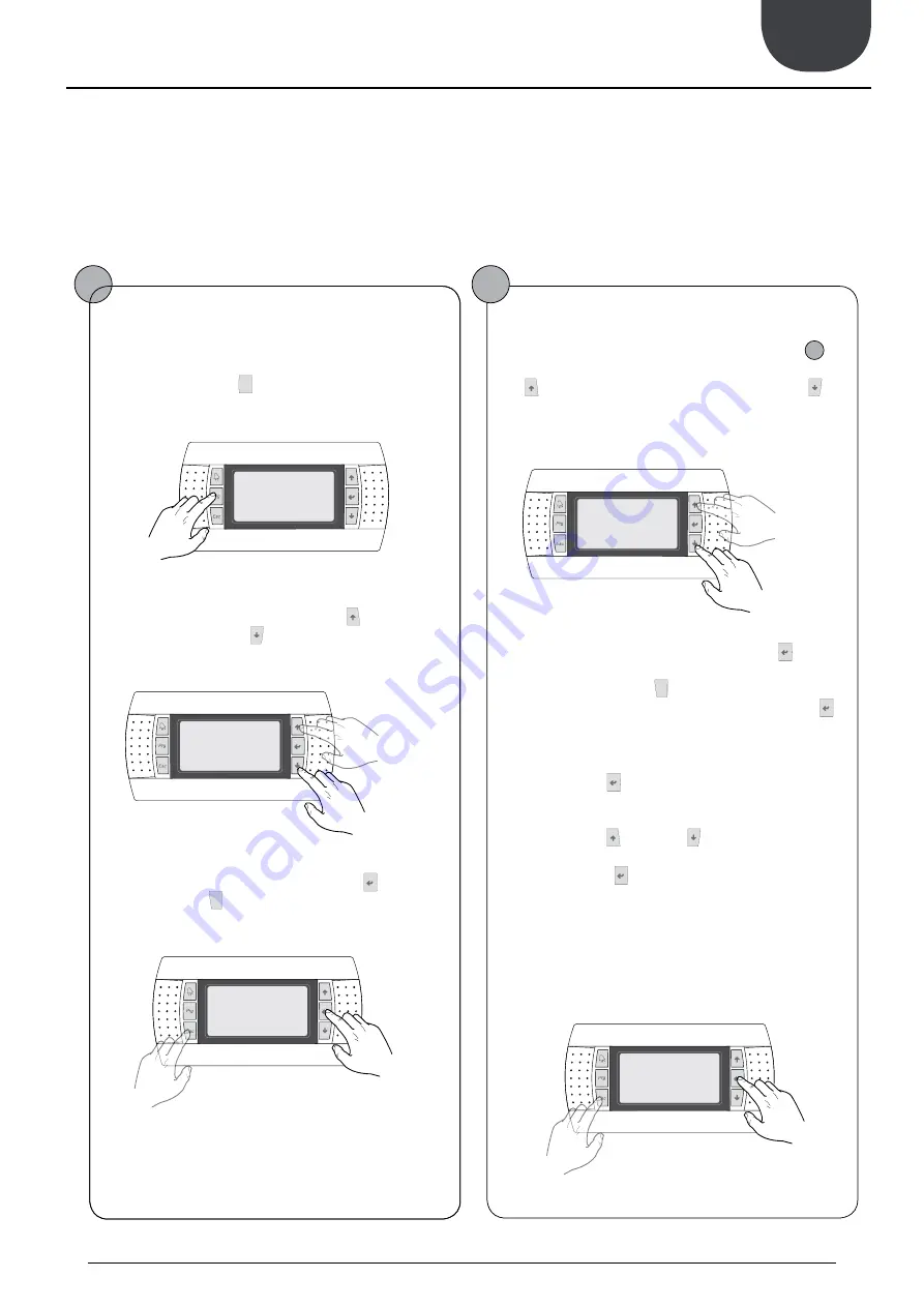
To check or modify the operati ng parameters of the unit it is necessary to use the interface of the control panel on the unit. The basic operati ons that the user must be
capable of, for the correct use of the unit, are:
(1) Moving from one menu to the next.
(2) Selecti ng and modifying a parameter.
User operating procedures
Moving between menus
(a) To move between the menus, the order in which they are dis-
played is shown in the previous page, enter the menu selection
mode by pressing the key (
).
(b) Once in the menu selection mode it is possible to move
between menus using the arrow keys: the key (
) to move to the
previous menu, and the key (
) to move to the next menu.
(c) When the desired menu is seen press the key (
)to enter the
menu. Press the key(
) to return to the menu selection mode.
Selecting and modifying a menu
(a) Once in the menu selected, by following the procedure (
1
), it
is possible to move between the screens using the arrow keys: the
key (
) to move to the previous parameter, and the key (
) to
move to the next parameter.
(c) When the desired parameter is seen press the key (
) to enter
the parameter. To exit the parameter and return to the parameter
selection mode press the key (
).
WARNING: Once a parameter is selected by pressing the key (
),
the parameter selection mode is automatically accessed and in this
mode the desired parameter values can be set with the following
procedure:
(1) Pressing the key (
) causes a flashing cursor to appear on the
first modifiable field of the parameter. If no modifiable fields are
displayed then the cursor will not appear.
(2) Pressing the key (
) or the key (
), the value of the field can
be increased or decreased.
(3) Pressing the key (
) confirms the modification of the field
value, saving it in memory. On the basis of the type of parameter
selected the number of modifiable fields can change.
previous menu
next
menu
exiting a menu
entering a
menu
previous para-
meter
next
parameter
exiting a
parameter
entering a para-
meter
16.
USER OPERATING PROCEDURES


