MAINTENANCE
7-3
The burner assembly is located at the top of the
unit. The burner assembly may be HOT. Allow
the unit to cool sufficiently before removing the
burner assembly.
The following parts will be necessary for
reassembly after inspection:
161432
Burner Gasket
161433
Burner Release Gasket
To inspect or replace the burner assembly:
1. Place the green ON/OFF button on the
control panel, to the OFF position and
disconnect AC power to the unit.
2. Remove the side and top panels from the
unit.
3. Disconnect the lead wire from the flame
detector.
4. Disconnect the ignitor cable from the ignitor
contactor.
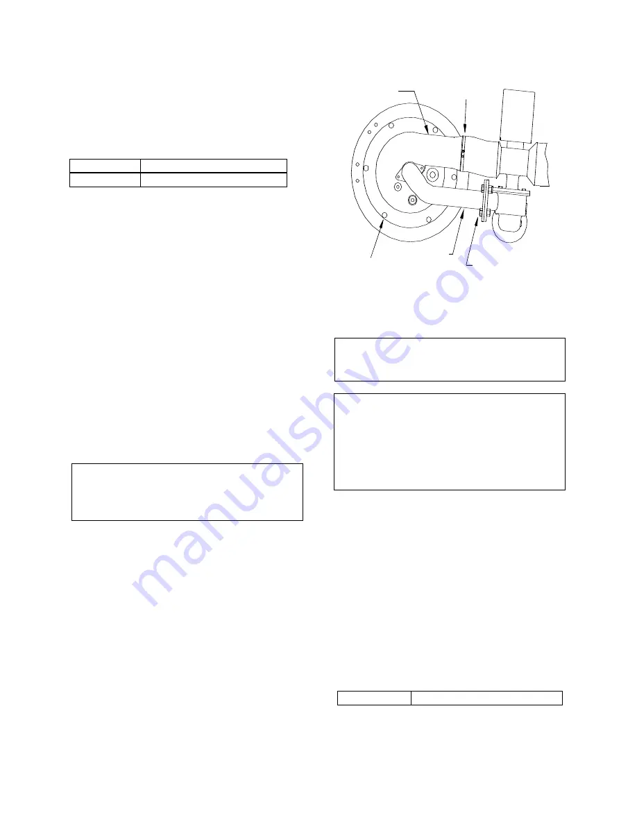
5. Disconnect the combustion air hose from the
burner by loosening the hose clamp.(See
Fig. 7.3)
6. Remove the four (4) 5/8-11 nuts and bolts
from the gas outlet side of the Air/Fuel
Valve. (See Fig 7.3).
NOTE:
It is best to leave the gas pipe attached to
the burner, as it will assist you in removing
the burner from the unit.
7. Remove the six (6) 5/16-16 bolts from the
burner flange. (See Fig 7.3)
8. Remove the burner from burner flange by
pulling straight up.
9. Remove and replace the burner release
gasket.
10. Remove and replace the burner gasket.
11. Beginning with the burner removed in step 8
of this section reinstall all the components in
the reverse order that they were removed.
BURNER
HOSE CLAMP
5/8-11 NUT & BOLT
5/16-16 BOLT
GAS PIPE
Figure 7.3
Burner Disassembly Diagram
NOTE:
The burner is heavy weighing approximately
25 pounds.
NOTE:
A complete inspection of the combustion
chamber tubes can not be performed at this
time. In order to completely inspect the
combustion chamber tubes you must
remove the exhaust manifold.
(See Sect 7.7)
7.7 EXHAUST MANIFOLD AND
COMBUSTION CHAMBER
The presence of even trace amounts of
chlorides and/or sulfur, in the combustion air and
fuel sources, can lead to the formation of
deposits on the inside of the exchanger tubes,
the exhaust manifold, and/or the condensate
trap. The degree of deposition is influenced by
the extent of the condensing operation and the
chloride and sulfur levels. Even trace amounts of
contaminants such as chlorides and sulfur void
the warranty.
The following parts will be necessary for
reassembly after inspection:
123612
Exhaust Manifold Gasket
To remove the manifold for inspection:
1. Disconnect AC power and turn off the gas
supply to the unit.
Содержание Benchmark G-00-711
Страница 62: ...APPENDIX C ix Temperature Sensor Resistance Chart Balco ...
Страница 69: ...APPENDIX F xvi ...
Страница 70: ...APPENDIX F xvii ...
Страница 71: ...APPENDIX F xviii ...
Страница 72: ...APPENDIX F xix ...
Страница 73: ...APPENDIX F xx ...
Страница 74: ...APPENDIX G xviii ...
Страница 75: ...APPENDIX G xix ...
Страница 76: ...APPENDIX H xxi ...


