28
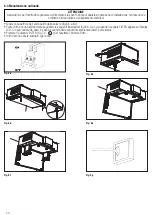
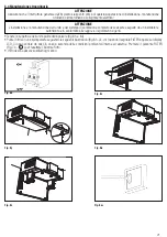
5.a.b
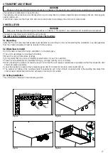
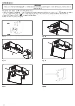
Prepare the surface where the unit is to be mounted. Make sure that the surface is flat, leveled and that it supports the
weight of the unit. Perform the installation in accordance with local rules and regulations.
Drill holes in the exterior wall for air intake and exhaust and holes for ceiling mounting.
5.c
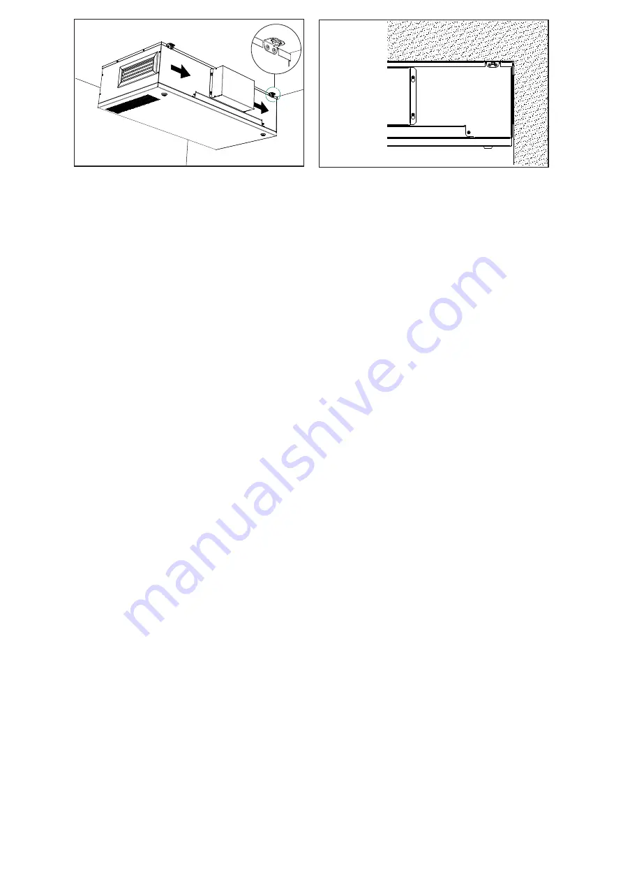
Fix the air intake and exhaust spigots into the wall.
5.d
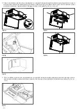
Use appropriate plugs and rods or screws (not supplied) to fix the unit to the ceiling, making sure that the two holes (for air
intake and exhaust) on the unit body are aligned with the fixed spigots. It is recommended to fit the unit with anti-vibration
mounts (not supplied).
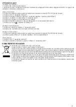
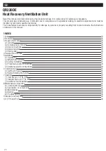
5.e.g
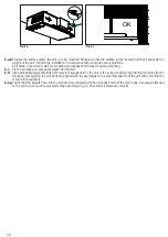
Check that the spigots fixed into the wall are duly coupled with the unit body and that the main body is securely attached
to the ceiling. Connect the unit electrically according to §5.4. Check that it starts up correctly.
A
DETAIL A
B
DETAIL B
OK!!
SCHEMI ELETTRICI
MESSA IN SERVIZIO
FUNZIONAMENTO
A
DETAIL A
B
DETAIL B
OK!!
SCHEMI ELETTRICI
MESSA IN SERVIZIO
FUNZIONAMENTO
Fig. 5.e
Fig. 5.f
A
DETAIL A
B
DETAIL B
OK!!
SCHEMI ELETTRICI
MESSA IN SERVIZIO
FUNZIONAMENTO
Содержание QR220DE
Страница 47: ...47 NOTE ...


