
36
Sentinel
™
Data Loggers
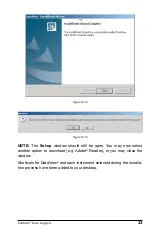
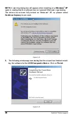
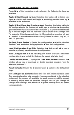
NOTE:
A warning dialog box will appear when installing on a
Windows
®
XP
system, stating that the software has not passed Windows Logo testing.
The drivers have been fully tested on Windows
®
XP, so please select
Continue Anyway
to proceed.
Figure 5-15
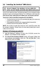
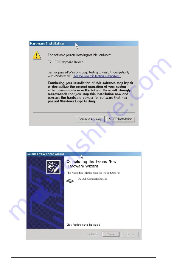
5.
The following window appears stating that the wizard has fi nished install-
ing the software for the
USB Composite Device
. Click on
Finish
.
Figure 5-16


