LBI-33057
RF BOARD - MODULE AND IC DATA
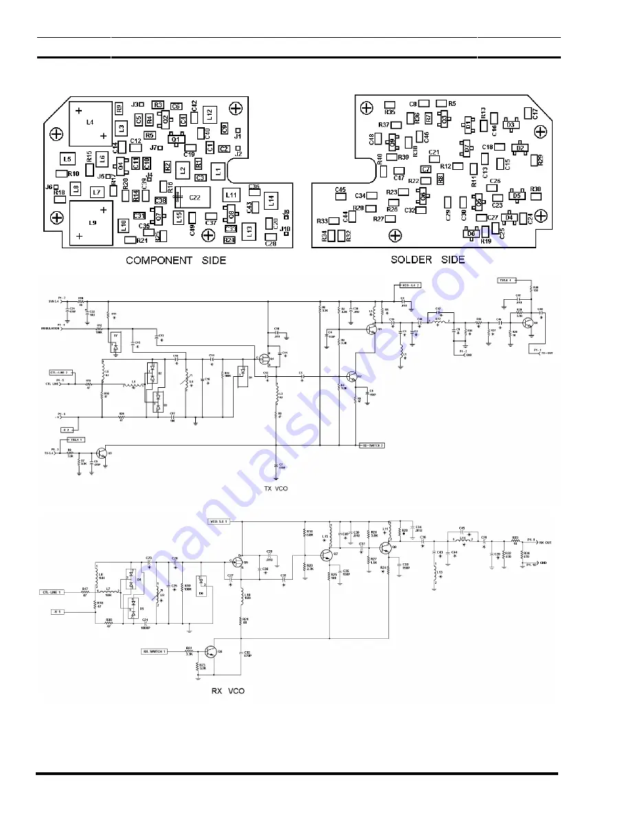
24
A4
(19D438605, Sh. 1, Rev. 2)
(19D438604, Sh. 1, Rev. 4)
(19D438604, Sh. 2, Rev. 3)
VCO19A438605
Страница 1: ...X CIRCUIT ACCESS 6 UDC flex UDC Monitor Button HT Switch Assembly Removal 7 Earlier Front Cover Assembly Keypad Flex Removal 7 Later Front Cover Assembly Keypad flex Removal 7 Speaker Flex Removal 7 L...
Страница 2: ...D COMPONENT 16 SURFACE MOUNTED INTEGRATEDCIRCUIT REPLACEMENT 17 MODULE REPLACEMENT 17 WEATHERPROOF INTEGRITY 17 BATTERY PACKS 17 CHARGING THE BATTERY PACKS 19 REDUCED CAPACITY CONDITION 19 CONTROL KNO...
Страница 3: ...dio Distortion Analyzer with Vu Meter Oscilloscope with x1 and x10 Probes Audio Oscillator Frequency Counter Modulation Analyzer SINAD Meter Regulated DC Power Supply 5 9 Vdc adjustable 5 amperes maxi...
Страница 4: ...points are provided for the volume control and mi crophone audio A resistor network on the Front Cover Test Cable provides a dc bias to the mic in the absence of the Control Board s bias DISASSEMBLY R...
Страница 5: ...her to ensure the gap is com pletely closed The bottom screws can then be tightened Figure 1 Front and Rear Cover Separation RF BOARD ACCESS Holes are located in the RF Board shield for align ment of...
Страница 6: ...s USE Figure 3 Control Board Access CAUTION Installation of screws that are longer than the originals may damage the LCD Board flex circuits or the threads To remove the Control Board remove the Torx...
Страница 7: ...ssembly Keypad flex Removal To remove the Keypad Flex first remove the UDC Flex UDC Monitor Button PTT Switch assembly as pre viously stated Next remove the screw securing the emer gency switch suppor...
Страница 8: ...he Front and Rear Cover Assemblies and connect the RF Logic Extender cable be tween the RF Board and the Control Board See Figure 6 2 Slide the Dummy Battery onto the Front Cover and connect the audio...
Страница 9: ...t channel listed in Table 2 low power and key the transmitter using the TQ 0609 DO NOT apply any modulation at this time 3 Monitor transmitter frequency and adjust Refer ence Oscillator U3 to a freque...
Страница 10: ...kHz deviation with a 1000 Hz tone RECEIVER ALIGNMENT The following information can be used to check and align the receiver circuits Successful completion of these alignment procedures will verify a n...
Страница 11: ...for each parameter using a linear interpolation technique The Programmer then stores the newly calculated values in the Channel Data area of memory along with the associated channel information Chang...
Страница 12: ...low pass filter circuit or antenna switch SWI If the low pass filter circuit or the antenna switch have a problem generally the receiver will also be weak A defective pin diode DI or D2 can cause tra...
Страница 13: ...itter inoperative or low range 1 Power levels programmed low Check RF output and reprogram unit if necessary 2 Weak battery Note BAT flag 3 Defective antenna 4 RF Board problem Troubleshoot Rear Cover...
Страница 14: ...Hz 1 5 kHz deviation RX DISC should be 100 150 mV rms approximately 350 mV p p If the 1 kHz audio is present troubleshoot the audio circuits in the Front Cover Assembly Noise levels on RX DISC with no...
Страница 15: ...is power source is not present check A5 pins 7 and 13 inputs for 5 5 Vdc and check A5 pin II input for 7 5 Vdc Replace A5 if the inputs are good and the output is not 4 Using a frequency counter with...
Страница 16: ...system is used direct the heat to the terminals of the component Use extreme care with the sol dering equipment to prevent damage to the printed wire board PWB and the surrounding components 3 When t...
Страница 17: ...ated through points at the appropriate pins If a hot air system is employed use an appropriate tip that will localize the heat on the pins and not on sur rounding chip components Solderwick or a vacuu...
Страница 18: ...LBI 33057 18 Figure 8 Battery Packs...
Страница 19: ...first discharge cycle the capacity may be significantly lowered reducing useful service hours The reduced capacity condition should be suspected on any rechargeable battery pack showing signs of re du...
Страница 20: ...positions are required do not reinstall the stop plate 4 Replace the Control Knob and torque the set screw per Table 1 The set screw must align on the flat area of the switch shaft Rotate the knob to...
Страница 21: ...annel 8 Couple a modulation analyzer with a monitor ing oscilloscope to the RF output of the radio Set the modulation analyzer s filters as follows no high pass filters and 20 kHz low pass filter The...
Страница 22: ...o the output of IF crystal filter FL2 ground and connect this cable to a spectrum analyzer tuned to 45 MHz and set to 2 dB division A less desirable alternative using the same tuning sequence can be a...
Страница 23: ...LBI 33057 RF BOARD MODULE AND IC DATA 23 A1 19C337063 Rev 1 19C337315 Rev 1 POWER CONTROLLER 19C337063 A2 19C337062 Rev 2 19C336876 Rev 0 IF AMPLIFIER 19C336876G1...
Страница 24: ...LBI 33057 RF BOARD MODULE AND IC DATA 24 A4 19D438605 Sh 1 Rev 2 19D438604 Sh 1 Rev 4 19D438604 Sh 2 Rev 3 VCO 19A438605...
Страница 25: ...LBI 33057 RF BOARD MODULE AND IC DATA 25 A5 19C852056 Sh 1 Rev 0 19C852057 Sh 1 Rev 1 PLL LOW PASS FILTER REGULATOR 19C852056G1...
Страница 26: ...LBI 33057 RF BOARD MODULE AND IC DATA 26 A6 19B235081 Sh 1 Rev 2 19C337073 Rev 1 UHF RF AMPLIFIER 19B235081 U1 SYNTHESIZER 19B800902P4...
Страница 27: ...LBI 33057 RF BOARD MODULE AND IC DATA 27 U2 PRESCALER 19A704287P2 U3 13 2 MHz REFERENCE OSCILLATOR 19B801351P15...
Страница 28: ...LBI 33057 RF BOARD MODULE AND IC DATA 28 U4 RF POWER AMPLIFIER 19A705419 U5 MIXER 19A705706P2 U6 RECEIVER BACKEND 19A704619P1...
Страница 29: ...LBI 33057 RF BOARD MODULE AND IC DATA 29 This page left intentionally blank...
Страница 30: ...Ericsson Inc Private Radio Systems Mountain View Road Lynchburg Virginia 24502 1 800 528 7711 Outside USA 804 528 7711 Printed in U S A...