


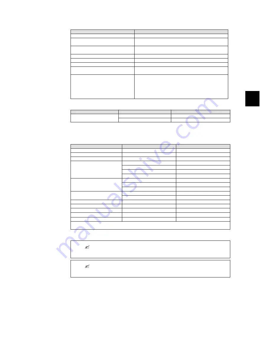
Parameter
Specification
Temperature
-25°C - +60°C (>45°C derating)
Environmental class according to IEC
IEC60721-3-3
3K6/3B3/3S3/3M2
Air quality
ISA S71.04-1985
Level G2 (at 75%RH)
Coastal, heavy industrial and farmer areas Must be measured and classified acc. to ISA S71.04-1985
Vibration
1G
Ingress protection class
54
Max. operating altitude
3000m above sea level.
PELV protection is effective up to 2000m above sea level only.
Installation
Avoid constant stream of water.
Avoid direct sunlight.
Ensure adequate air flow.
Mount on non-flammable surface.
Mount upright on vertical surface.
Prevent dust and ammonia gases.
Table 5.3: Conditions for Installation
Parameter
Condition
Specification
Wall Plate
Hole diameter
30 x 9 mm
Alignment
Perpendicular ± 5° all angles
Table 5.4: Wall Plate Specifications
5.1.1. Cable Requirements
Cable
Condition
Specification
AC
5 wire cable
Copper
Outer diameter
18-25 mm
Insulation strip
All 5 wires
16 mm
Max. recommended cable length
Protect PV 10
2.5 mm
2
21 m
4 mm
2
34 m
6 mm
2
52 m
10 mm
2
87 m
Max. recommended cable length
Protect PV 12.5
4 mm
2
28 m
6 mm
2
41 m
10 mm
2
69 m
Max. recommended cable length
Protect PV 15
6 mm
2
34 m
10 mm
2
59 m
PE Cable diameter
at least
as phase cables
DC
Max. 1000 V, 12 A
Cable length
4 mm
2
- 4.8
Ω
/km
< 200 m*
Cable length
6 mm
2
- 3.4
Ω
/km
>200-300 m*
Mating connector
Multi-contact
PV-ADSP4./PV-ADBP4.
* The distance between inverter and PV array and back, plus the summarised length of the cables used for
PV array installation.
Table 5.5: Cable Requirements
Note:
Avoid power loss in cables of more than 1 % of nominal inverter rating.
Note:
In France, observe the UTE C 15-712-1 and NF C 15-100 requirements.
5. Technical Data
8000038781_00_BAL_en / L00410564-01_02
25
5