AEG Protect PV Скачать руководство пользователя страница 21

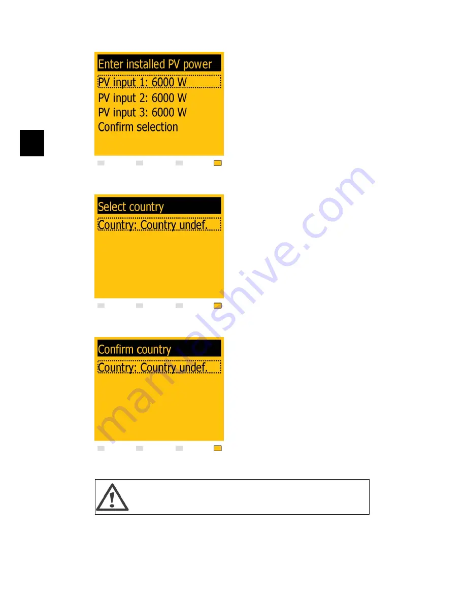
Illustration 4.4: Installed PV Power

Enter  the  amount  of  installed  PV  power  for
each of the PV inputs. When two or more PV
inputs are connected in parallel, each PV in-
put in the parallel group must be set to the
total  amount  of  PV  power  installed  to  that
group  divided  by  the  number  of  parallel  in-
puts. See the table below for examples of in-
stalled PV power.

Illustration 4.5: Select Country

The  display  will  now  show  “Select  country”.
The  country  is  set  to  “undefined”  at  initial
start-up. To select country press 'OK'. Press ‘

  ’  to  scroll  down  through  the  list  of  coun-

tries. Select the country in which the inverter
is  installed  by  pressing  ‘OK’.  To  meet  medi-
um voltage grid requirements select a coun-
try option ending in MV. It is very important
that the correct country is chosen.

Illustration 4.6: Confirm Country Selection

Confirm  the  choice  by  selecting  the  country
again  and  press  'OK’.  The  settings  for  the
chosen country have now been activated.

The inverter only complies with local and national standards provided the correct
country has been selected. If a different country than the one the inverter is in-
stalled in is chosen it can have serious consequences.

4. Start-up and Check of Settings


20


 8000038781_00_BAL_en / L00410564-01_02 


4

Содержание Protect PV

Страница 1: ...Protect PV Solar Inverters Installation Manual AEG Power Solutions GmbH Revision 01 Date 2011 05 25 Installation Manual 8000038781_00_BAL_en ...

Страница 2: ...g the Inverter 10 Removing the Inverter 11 Opening and Closing the Inverter 12 AC Grid Connection 14 PV Connection 16 Auxiliary Input Output 17 Autotest Procedure Italy Only 17 4 Start up and Check of Settings 18 Start up and Check of Settings 18 Troubleshooting 21 Master Mode 21 5 Technical Data 23 Technical Data 23 Cable Requirements 25 Wiring Diagram 28 Auxiliary Interface Specifications 29 RS4...

Страница 3: ...llation Safety information important for human safety Violation of warnings may result in injury to persons or death Information important for the protection of property Violation of this type of in formation may cause damage and loss of property Note Useful additional information or Tips and Tricks on specific subjects Read this before installing operating or maintaining the inverter 1 Safety and...

Страница 4: ...s not guaran teed Also observe the danger of burn injury The temperature of the cooling racks and components inside the inverter may exceed 70ºC Functional safety parameters Never change the parameters of the inverter without authorisation from the local energy supply company and instructions from AEG PS Unauthorised changes of functional safety parameters may cause injury or acci dents to people ...

Страница 5: ...oad area at www aegps com solarinverters Approvals and Certifications CE marking This certifies the conformity of the equipment with the regula tions which apply in accordance with the directives 2004 108 EC and 2006 95 EC 1 Safety and Conformity 4 8000038781_00_BAL_en L00410564 01_02 1 ...

Страница 6: ...15 kW CE marking This certifies the conformity of the equipment with the regula tions which apply in accordance with the directives 2004 108 EC and 2006 95 EC The Protect PV inverter series comprises Protect PV Protect PV easy Common features of the Protect PV variants Output rating of 10 kW 12 5 kW or 15 kW IP 54 enclosure PV load switch MC4 connectors 2 Introduction 8000038781_00_BAL_en L0041056...

Страница 7: ...ing and Closing the Inverter 4 Install AC according to the section AC Grid Connection 5 Install PV Remember to use the terminal block to establish parallel connection if re quired as described in the section PV Connection The inverter has auto detection 6 Install Auxiliary input according to the section Connection of Peripheral Units 7 Close the inverter according to the section Opening and Closin...

Страница 8: ...tion 4 Auxiliary output Potential free relay PELV Safe to touch 5 Auxiliary interface RS485 6 Auxiliary interface Temperature Irradiation Energy meter SO 7 Auxiliary interface Ethernet Other 8 DC switch The inverter can also be configured via the Web Server For further information refer to the Web Server User Manual 2 Introduction 8000038781_00_BAL_en L00410564 01_02 7 2 ...

Страница 9: ...e visible at all times For details refer to the section Specifications Avoid constant stream of water Avoid direct sunlight Ensure adequate air flow Ensure adequate air flow Mount on non flammable surface Mount upright on vertical surface Prevent dust and ammonia gases 3 Installation 8 8000038781_00_BAL_en L00410564 01_02 3 ...

Страница 10: ...ion on mounting in more rows Illustration 3 2 Wall Plate Note Use of the wall plate delivered with the inverter is mandatory Use screws that can safely carry the weight of the inverter The inverter must be aligned and it is important that the inverter is accessible at the front to allow room for servicing 3 Installation 8000038781_00_BAL_en L00410564 01_02 9 3 ...

Страница 11: ... Inverter Tilt the inverter as shown in the illustration and place the top of the inverter against the mounting bracket Use the two guides 1 at the top plate to control the inverter horizon tally Illustration 3 4 Secure the inverter Lift the inverter upwards 2 over the top of the mounting plate until the inverter tilts to wards the wall 3 3 Installation 10 8000038781_00_BAL_en L00410564 01_02 3 ...

Страница 12: ...ok of the inverter base plate is placed in the lower part of the mounting bracket 5 Check that it is not possible to lift the bottom of the inverter away from the mount ing bracket 6 Fasten the screws on either side of the wall plate to secure the inverter 3 3 Removing the Inverter Loosen the locking screws on either side of the inverter 3 Installation 8000038781_00_BAL_en L00410564 01_02 11 3 ...

Страница 13: ...verter away from the wall plate 3 4 Opening and Closing the Inverter Remember to observe all ESD safety regulations Any electrostatic charge must be discharged by touching the grounded housing before handling any electronic com ponent Illustration 3 7 Loosen Front Screws Use a TX 30 screwdriver to loosen the two front screws Turn the screwdriver until the screws pop up They are secured with a spri...

Страница 14: ...ecommended to use the holding position instead of dismounting the front cover completely Illustration 3 9 Close the Inverter To close the inverter hold on to the lower end of the front cover with one hand and give it a tap on the top until it falls into place Guide the front cover into place and fasten the two front screws 3 Installation 8000038781_00_BAL_en L00410564 01_02 13 3 ...

Страница 15: ... to the front cover Make sure that both screws are mounted and fastened with the specified torque 3 5 AC Grid Connection Note When choosing the installation place ensure that all labels are visible at all times For details refer to the section Specifications 3 Installation 14 8000038781_00_BAL_en L00410564 01_02 3 ...

Страница 16: ...llustration 3 12 AC Connection Area 1 Verify the inverter matches the grid voltage 2 Release main circuit breaker and make precautions to prevent reconnection 3 Open the front cover 4 Insert the cable through the AC gland to the terminal blocks 5 The three mains wires L1 L2 L3 and the Neutral wire N are mandatory and must be connected to the 4 pole terminal block with the respective markings 3 Ins...

Страница 17: ... maximum voltage of the PV arrays by measuring the PV open circuit voltage The PV open circuit voltage must not exceed 1000 V DC 2 Measure the DC voltage between the plus terminal of the PV array and Earth or the green yellow PE cable The voltage measured should approximate zero If the voltage is constant and not zero there is an insulation failure somewhere in the PV array 3 Locate and fix the fa...

Страница 18: ...ower than the max input voltage of the inverter see the specifications multiplied with a factor of 1 13 UOC STC x 1 13 UMAX inv 3 7 Auxiliary Input Output Note When choosing the installation place ensure that all labels are visible at all times For details refer to the section Specifications The inverter has the following auxiliary input output 2 x RJ45 for RS485 2 x RJ45 for Ethernet 1 x 8 pole t...

Страница 19: ...on It is always possible to see the applied country limits in the display The inverter accounts for daylight saving automati cally After installation check all cables and then close the inverter Turn on AC at the mains switch When prompted by the display select language This selection has no influence on the operating parameters of the inverter and is not a country selection Illustration 4 1 Selec...

Страница 20: ... time and date accurately as the inverter uses this for logging If a wrong time date is accidentally set correct it immediately in the set date and time menu Setup Inverter details Set date and time Illustration 4 3 Set Date Set date as prompted by the display Press OK to select Press to scroll up through the numbers Select by pressing OK 4 Start up and Check of Settings 8000038781_00_BAL_en L0041...

Страница 21: ...ess to scroll down through the list of coun tries Select the country in which the inverter is installed by pressing OK To meet medi um voltage grid requirements select a coun try option ending in MV It is very important that the correct country is chosen Illustration 4 6 Confirm Country Selection Confirm the choice by selecting the country again and press OK The settings for the chosen country hav...

Страница 22: ...PV 3 4000 W PV1 and PV2 are set into parallel mode and have a total of 11 kW PV power installed PV3 is set to Off and has no PV installed PV 1 5500 W PV 2 5500 W PV 3 0 W Table 4 1 Examples of Installed PV Power Note To meet medium voltage grid requirements select a country option ending in MV 4 2 Troubleshooting For information on Troubleshooting please see the Protect PV Reference Manual 4 3 Mas...

Страница 23: ...erter details Master mode and set Master mode to Ena bled Ensure that no other master inverters are present in the network prior to carrying out this action When Master mode is enabled it is possible to initiate a network scan Setup Inverter details Master mode Network This will show all inverters connected to the master inverter 4 Start up and Check of Settings 22 8000038781_00_BAL_en L00410564 0...

Страница 24: ...2 A Min on grid power 20 W 20 W 20 W Efficiency Max efficiency 98 98 98 Euro efficiency V at dc r 97 0 97 3 97 4 Other Dimensions L W H 700x525x250 mm 700x525x250 mm 700x525x250 mm Mounting recommendation Wall bracket Wall bracket Wall bracket Weight 35 kg 35 kg 35 kg Acoustic noise level4 56 dB A 56 dB A 56 dB A MPP trackers 2 3 3 Operation temperature range 25 60 C 25 60 C 25 60 C Nom temperatur...

Страница 25: ...D661 Reactive Power Protect PV and Protect PV easy Protect PV 10 kW Protect PV 12 5 kW Protect PV 15 kW Austria TOR Hauptabschnitt D4 TOR Hauptabschnitt D2 Belgium Synergrid C10 11 revisie 12 mei 2009 Synergrid C10 17 revisie 8 mei 2009 Czech Republic Czech Energy Act Act No 458 2000 Article 24 Paragraph 10 part I II III rev09 2009 France UTE NF C 15 712 1 UNION TECHNIQUE DE L ELECTRICITE GUIDE PR...

Страница 26: ... Table 5 4 Wall Plate Specifications 5 1 1 Cable Requirements Cable Condition Specification AC 5 wire cable Copper Outer diameter 18 25 mm Insulation strip All 5 wires 16 mm Max recommended cable length Protect PV 10 2 5 mm2 21 m 4 mm2 34 m 6 mm2 52 m 10 mm2 87 m Max recommended cable length Protect PV 12 5 4 mm2 28 m 6 mm2 41 m 10 mm2 69 m Max recommended cable length Protect PV 15 6 mm2 34 m 10 ...

Страница 27: ...5 2 Protect PV 12 5 kW Cable Losses versus Cable Length m Illustration 5 3 Protect PV 15 kW Cable Losses versus Cable Length m Consider also the following when choosing cable type and cross sectional area Ambient temperature 5 Technical Data 26 8000038781_00_BAL_en L00410564 01_02 5 ...

Страница 28: ... small Straight slot 0 5x3 0 mm 0 5 Nm 4 Terminal blocks large Straight slot 1 0x5 5 mm Min 1 2 Nm 5 PE Straight slot 1 0x5 5 mm 2 2 Nm 6 M16 SW 19 mm 2 3 Nm 7 M25 SW 30 mm 2 3 Nm Table 5 6 Nm Specifications Protect PV 10 kW Protect PV 12 5 kW Protect PV 15 kW Maximum inverter current 15 A 19 A 22 A Recommended fuse type gL gG 16 A 20 A 25 A Table 5 7 Mains Circuit Specifications 5 Technical Data ...

Страница 29: ...5 1 2 Wiring Diagram Illustration 5 5 Typical Installation 5 Technical Data 28 8000038781_00_BAL_en L00410564 01_02 5 ...

Страница 30: ...tance temperature coefficient 3 85 Ω oC Measurement range 20 oC 100 oC Measurement accuracy 3 Direct contact protection Double Reinforced insulation Yes Short circuit protection Yes Irradiation sensor input x 1 Cable specification Cable jacket diameter 4 8 mm Cable type Shielded Single Pair Number of wires depend on the sensor type used Cable shield termination Via EMC cable clamp Maximum wire gau...

Страница 31: ...ial for all peripheral cables To ensure EMC compliance shielded cables must be applied for Sensor inputs and RS485 communication Unshielded cables may be applied for alarm outputs Other auxiliary cables must pass through the designated EMC cable clamps to es tablish mechanical fixing and in case of shielded cable termination to the shielding device Parameter Condition Specification Potential free ...

Страница 32: ...Ethernet 10Base TX and 100Base TX auto cross over Table 5 10 RJ45 Pinout Detail Note The RS485 communication bus must be terminated at both cable ends Note The two network types cannot be mixed The inverters can only be connected in networks which are either solely RS485 or solely Ethernet Note Each inverter has a unique RS485 address when it is delivered This address is defined at the time of pro...

Страница 33: ...ax 420 274 773 265 Email service cz aegps com Spain AEG Power Solutions SL Parque Tecnologico de Alava C Albert Einstein 31 01510 Minano Alava Tél 34 66 990 31 12 Fax 34 945 21 41 11 Email service es aegps com Netherlands AEG Power Solutions Weerenweg 29 1161 AH Zwanenburg Tel 31 20 40 77 818 821 Tel outside office hours 31 20 40 77 866 Fax 31 20 40 77 801 Email service nl aegps com Germany AEG Po...

Отзывы: