background image

55

• The air outlet must not be connected to chimney flues or combustion

gas ducts. The air outlet must under no circumstances be connected

to ventilation ducts for rooms in which fuel-burning appliances are

installed.

• The air outlet installation must comply with the regulations laid down

by the relevant local authorities.

• When the unit is used in extraction mode, a sufficiently large

ventilation hole must be provided, with dimensions that are approxi-

mately the same as the outlet hole.

• National and regional building regulations impose a number of

restrictions on using hoods and fuel-burning appliances connected to

a chimney, such as coal or oil room-heaters and gas fires, in the

same room.

• Hoods can only be used safely with appliances connected to a

chimney if the room and/or flat (air/environment combination) is

ventilated from outside using a suitable ventilation hole approximately

500-600 cm

 large to avoid the possibility of a depression being

created during operation of the hood.

• If you have any doubts, contact the relevant controlling authority or

building inspector’s office.

• Since the rule for rooms with fuel burning appliances is “outlet hole of

the same size as the ventilation hole”, a hole of 500-600 cm

2

, which

is to say a larger hole, could reduce the performance of the extractor

hood.

• If the hood is used in its recirculation mode, it will operate simply

and safely in the above conditions without the need for any of the

aforementioned measures.

• When the hood is used in its extraction mode, the following rules

must be followed to obtain optimal operation:

- short and straight outlet hose

- keep bends in outlet hose to a minimum

- never install the hoses with an acute angle, they must always

follow a gentle curve.

- keep the hose as large as possible (preferably the same diameter

as the outlet hole).

- the length should be no more than:

3 metres with one 90° bend

2 metres with two 90° bends

Bends of more than 90° will reduce the efficiency of the hood and

reduce the airflow.

• Failure to observe these basic instructions will drastically reduce the

performance and increase the noise levels of the extractor hood.

Содержание DE 3160

Страница 1: ...DE 3160 Dunstabzugshaube Afzuigkap Hotte Cooker Hood Montage und Gebrauchsanweisung Installatie en gebruiksaanwijzing Notice d utilisation et d installation Operating and Installation Instructions ...

Страница 2: ...hood 59 Grease Filter 59 Opening the grid 60 Removing the filter 60 Charcoal filter 61 Changing the light bulb 62 What to do if 63 Special accessories 64 Technical assistance service not for UK 64 Technical Specifications 66 Mounting accessories included 66 Electrical connection 67 Installing the hood between cabinets 68 Installing the hood to the wall 69 Fixing a furniture door to the visor 70 ...

Страница 3: ...ircuit breaker It is very important to clean the hood and replace the filter at the recommended intervals Failure to do so could cause grease deposits to build up resulting in a fire hazard The appliance is not intended for use by young children or infirm persons without supervision Older children must be supervised if using the appliance Young children should be supervised to ensure that they do ...

Страница 4: ...ted during operation of the hood If you have any doubts contact the relevant controlling authority or building inspector s office Since the rule for rooms with fuel burning appliances is outlet hole of the same size as the ventilation hole a hole of 500 600 cm2 which is to say a larger hole could reduce the performance of the extractor hood If the hood is used in its recirculation mode it will ope...

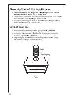
Страница 5: ...er You will need an original charcoal filter for this function Available from your local Service Force Centre Extraction mode In this mode fumes are extracted to the outside via a hose connected to the coupling ring Fig 1 In order to obtain the best performance the hose should have a diameter equal to the outlet hole Depending on your installation the hose can be directed either towards the ceilin...

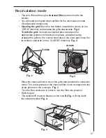
Страница 6: ... it latches into place and after having propped the grille to the cooker hood also in the lower part move the two sliders outwards in the CLOSED direction Fig 2 Place the charcoal filter to cover the grille that protects the extraction motor The arrow printed on the charcoal filter must correspond to the arrow printed on the conveyor Fig 3 Turn the filter clockwise in order to lock the filter into...

Страница 7: ...n the hood s front panel the light switch switches the hood lamp on and off the motor switch switches the motor on and off enabling you to select one of the three different speeds The hood is also equipped with a micro switch which can be found under the lower runner of the visor on the right hand side With this micro switch the appliance may be automatically switched on and off by opening and clo...

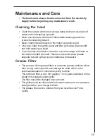
Страница 8: ...extremely important to clean the unit and change the filters at the recommended intervals Failure to do so will cause grease deposits to build up that could constitute a fire hazard Grease Filter The purpose of the grease filters is to absorb grease particles which form during cooking and it must always be used either in the external evacuation or internal recycling function The synthetic filter i...

Страница 9: ...until it latches into place and after having propped the grille to the cooker hood also in the lower part move the two sliders outwards in the CLOSED direction Removing the filter Remove the stops to take out the filter Fig 5 Clean the inner housing using a hot detergent solution only never use caustic detergents abrasive powders or brushes Fig O P E N C L O S E D O P E N C L O S E D Guides Stops ...

Страница 10: ... Fitting the charcoal filter Remove the grid Place the charcoal filter to cover the grille that protects the extraction motor The arrow printed on the charcoal filter must correspond to the arrow printed on the conveyor Fig 6 Turn the filter clockwise in order to lock the filter into position Refit the grid To remove proceed in the reverse order Always specify the hood model code number and serial...

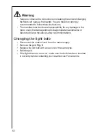
Страница 11: ... for any damage to the motor or any fire damage linked to inappropriate maintenance or failure to observe the above safety recommendations Changing the light bulb Disconnect the cooker hood from the mains supply Remove the grid Fig 5 Replace the old bulb with a new one of the same type Refit the grid If the light does not come on make sure the bulb has been inserted in correctly before contacting ...

Страница 12: ...that the ducting and outlets are not blocked The cooker hood has The safety cut out device has switched off during operation been tripped Turn off the hob and then wait for the device to reset If the hood has been installed below the heights indicated in the installation instructions the motor will cut out frequently which will damage the hood If after all these checks the problem persists contact...

Страница 13: ...arts contact your local Service Force Centre by telephoning 08705 929 929 Your call will be automatically routed to the Service Centre covering your post code area For the address of your local Service Force Centre and further information about Service Force please visit the website at www serviceforce co uk Please ensure that you have read the section What to do if as the engineer will make a cha...

Страница 14: ...ice eid electrolux ie CUSTOMER CARE DEPARTMENT For general enquiries concerning yourAEG appliance or for further information onAEG products please contact our Customer Care Department by letter or telephone at the address below or visit our website at www aeg co uk CustomerCareDepartment AEG 55 77 High Street Slough Berkshire SL1 1DZ 08705 950950 calls to this number may be recorded for training p...

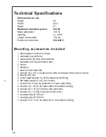
Страница 15: ...ixing a furniture door 2 hooks 1 deflector 1 spacer lower bracket 2 screws 3 5 x 9 5 e 2 washers to affix the spacer to the cooker hood 4 dowels Ø 8 mm 2 round head screws 5 x 45 for spacer wall fixing 2 flat head screws 5 x 45 for hooks 1 screw 2 9 x 9 5 to fix deflector on hood outlet hole 2 screws 4 2 x 35 to fix hood under the cabinet ceiling 4 screws 4 5 x 16 for fixing to side cabinets 8 scr...

Страница 16: ...ipolar disconnector with a distance of at least 3 mm between contacts must be provided Fixed connection of the appliance must only be carried out by an authorised electrician Electrical connection for UK only Safety warnings for the electrician Connect the hood to the mains supply via a double pole switch which has 3 mm minimum separation between the contacts The switch must be accessible at all t...

Страница 17: ...T DOOR Fasten the cooker hood with 4 screws Fig 7 P place the connection ring and discharge pipe or deflector if supplied to the cooker hood outlet see Use section mount the lower bracket Fig 7 9 Q to the cooker hood with two screws and plastic washers Fig 9 T Attention If required the hood can be fixed to an existing cabinet top with two screws be sure to leave passage for exhaust hose or for rec...

Страница 18: ...ulate the position of the cooker hood Fig 9 screws S1 for vertical regulation screws S2 for depth regulation Place connection ring and discharge pipe or deflector if supplied to the cooker hood outlet see Use section fasten the cooker hood to the lower bracket Fig 7 9 Q with two screws and plastic washers Fig 9 T Access to the screws that secure the lower bracket may be through the drill holes loc...

Страница 19: ...cated K Fig 11 Place the visor over the furniture door and affix with 8 screws Fig 11 L Refit the cover on the cooker hood firstly in the upper track Fig 12 M1 then in the lower track Fig 12 M2 Where the cooker hood is provided with revolving locking releases these should be turned in the opposite direction of the release to ensure that the visor is not unintentionally released during normal use o...

Страница 20: ...71 ...

Страница 21: ...lectrolux Group products such as refrigerators cookers washing machines vacuum cleaners chain saws and lawn mowers are sold each year to a value of approx USD 14 billion in more than 150 countries around the world LI2J2A Ed 12 04 AEG Hausgeräte GmbH Postfach 1036 D 90327 Nürnberg http www aeg hausgeraete de Copyright by AEG AEG 55 77 High Street SLOUGH Berks SL11DZ http www aeg co uk ...

Отзывы: