background image

Unmanned Aircraft System 

       Professional

·

Advanced


- 60 - 

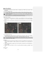
red power indicator turns on, and the antenna begins initialization; the initialization is finished when the antenna 
faces south. As to the method for connecting the auto tracking antenna to the ground station software, please see 
the section of “Use the Ground Station Software — Auto Tracking Antenna Connection Serial Port” on Page 43.     


Notice: 1. When using the auto tracking antenna, please keep away from areas subjected to intense 

electromagnetic interference. 

2. When connecting the auto tracking antenna to the ground station software, please first turn on the 

power switch of the auto tracking antenna and then open the ground station software.     


Shut Down the Auto Tracking Antenna


First, close the ground station GS software; then, turn off the power switch of the auto tracking antenna, and 
disconnect the communication cable, radio antenna extension cable and video antenna extension cables.   
Warning: When disconnecting the communication cable of the auto tracking antenna, please first pull the aviation 
plug shell outward, and then pull out the plug.   
 

Video Files     

After startup, the UAV will automatically enter the video recording state. The user can preview the video on the 
screens of the remote control and the ground station. When the UAV is shut down, recording will be stopped and 
video files saved automatically. Using a USB data cable, you can copy the video files in the UAV to a PC for 
playback. The real-time videos sent back by the UAV can be saved to the memory of the remote control by pressing 
the “Local Recording” button of the remote control or the ground station. For detailed operation methods, please 
refer to the section of “Description of Buttons” of the remote control and the ground station.   
 

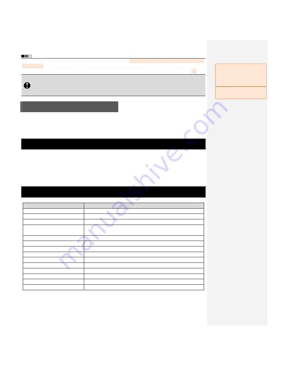
Specification   


Description  

Specification  

Fly mode   

Manual remote control, autonomous hover, autonomous route 

No-load take-off weight   

7.8kg (with battery) 

Load capacity 

4.5kg  

Endurance time   

40min (20,000mAh battery) 
30min (15,000mAh battery) 

Maximum cruising speed   

15m/s (not suggested) 

Maximum remote control range   

10km   

Maximum flying range   

20km   

Flight altitude (relative altitude) 

Max. 3,000m   

Climbing speed   

8m/s 

Normal take-off/landing wind speed   

Below Level 6 

Working temperature  

-10°C ~ +50°C  

Working humidity   

0% ~ 95%RH 

Storage temperature   

-20°C ~ +60°C 

Airborne camera   

HD camera with two-axis PTZ   


批注


[e6]:


原稿:天线

面朝南


方,初始化完毕。 

是指天线

面朝南

方时,初始化完毕

吗? 

批注


[e7]:


原稿:

P41


译稿中该部分是在

43

页上


Содержание F100A

Страница 1: ...Unmanned Aircraft System Professional Advanced Unprecedented Technology User s Manual Please read this Manual carefully before use and keep it handy for future reference ...

Страница 2: ... Guide for Components of the UAV 10 Install the Propeller Blades 12 Install the Removable Arms 12 Install the Airborne Camera 13 Install the Power Battery of the UAV 14 Preparations before Take off 15 Control the Flight with the Remote Control 16 Guide for Components of the Remote Control and Description of Button Functions 16 Preparations for the Remote Control 18 Parameter Setting for the Remote...

Страница 3: ...ith the Ground Station 39 Use the Ground Station Software 41 Functions of Video Capture Window in the Ground Station Software 50 Map Backup 54 Auto Tracking Antenna 56 Guide for Components of the Auto Tracking Antenna 56 Install the Tripod 57 Install the Antenna 58 Connect the Radio and Video Antenna Extension Cables 58 Connect the Communication Cable 59 Start up the Auto Tracking Antenna 59 Shut ...

Страница 4: ......
Страница 5: ...ons Stable and reliable this system can be operated in a simple and flexible way It can easily realize editing of waypoints on a 3D map setting of air routes real time sending back such information as coordinates flight attitude speed and video It can also meet the shooting requirements for multi dimensional investigation and monitoring The product is widely applied in such missions as military re...

Страница 6: ...ff position of the UAV to avoid intersection between the air route and mountains or buildings which may result in collision between the UAV and the said mountains or buildings during flight along the air route If the map fails to be loaded when the ground station software is started please close the software connect to the network and restart the software or make use of data management of Google M...

Страница 7: ...tery of the UAV is sent the UAV will automatically land at the current position rather than go home at this moment you can switch to the manual mode so that the UAV will go home In case of level 1 alarm for low battery of the UAV or level 2 alarm for low battery of the remote control or ground station please decide whether the flight can proceed with caution it is suggested that the flight should ...

Страница 8: ...r and professional control software This charger can be used to charge four batteries simultaneously Please connect the battery to the charger according to the following steps Step Illustration Description Step 1 Connect the two charger wires according to the figure and pay attention to the polarity of terminals Step 2 Select the charging port corresponding to the number of the cells 6S for power ...

Страница 9: ...e begins to pulsate press DEC or INC to select the corresponding voltage of the battery press START for confirmation after the voltage is adjusted to 25 2V 5 After setting all parameters long press START for 2s and the charger begins to detect the battery after successful detection press START to start charging 3 Complete charging of the battery After charging is completed the charger sends out be...

Страница 10: ...y result in swelling fluid leaking cell breakdown or even explosion of the battery 9 Do not connect the battery in reverse polarity 10 Any waste battery should be recycled in an environment friendly way 11 If the battery will be idle for a long time the battery should be taken out and charged once every six months to 24V for storage so as to maintain the battery performance and prolong its service...

Страница 11: ...pter then insert the adapter plug into the power outlet Insert the other end of the adapter to the charging jack of the ground station clockwise rotate the metal ring on the charging plug to make the charging plug in close contact with the charging jack without looseness 2 Charging state During charging of the ground station the charging indicator light is red when it is charged fully the charging...

Страница 12: ... or damage please feel free to contact us No Name Illustration Quantity Description 1 Main unit of aircraft 2 sets 2 Main unit of remote control 1 set 3 Main unit of ground control station 1 set 4 Auto tracking antenna 1 set 5 Undercarriage 4 sets 2pcs set 6 Propeller 4 sets 4pcs set Include 64pcs of screw 7 Power battery for flight 4pcs 2pcs of 20 000mAh battery and 2pcs of 15 000mAh battery 8 Ba...

Страница 13: ...Include power cord charger connecting cable 12 Battery voltage indicator 2pcs 13 Radio antenna 2pcs 14 Video antenna 4pcs 15 HDMI output cable 2pcs 16 Wrench 14mm For installing the auto tracking antenna 17 Screwdriver 2 5mm 1pc For removing the propellers 18 AV output cable 2pcs 19 USB data cable 3pcs ...

Страница 14: ...only Unmanned Aerial Vehicle The unmanned aircraft system integrates the flight control software radio modem HD image transmission control joysticks mission control buttons etc enabling users to conveniently view flight data and real time images during flight through control by the remote control or ground station the UAV can realize spot hover routed flight and other types of real time route moni...

Страница 15: ...able arm A1 4 Frame arm A1 5 Frame arm B2 6 Removable arm B2 7 Power key 8 Undercarriage 9 Airborne camera 10 Propeller 11 Removable arm B1 12 Frame arm B1 13 Frame arm A2 14 Removable arm A2 15 Power indicator 16 Battery plug switch Configuration of F100 main unit system ...

Страница 16: ...d with letter R on the removable arms B1 and B2 respectively as directed by the dashed lines in the figure below use the supplied screwdriver to tighten the set screws by applying proper force note that screw glue should not be used Notice Wrong installation of clockwise and counter clockwise propeller blades will inevitably result in errors in the UAV lift system further leading to unpredictable ...

Страница 17: ...PTZ control cable to the airborne camera insert the white HDMI cable into the port marked with a white block as shown in the figure below 3 Attach the two clamping pins of the PTZ as shown in the red circles by aligning with the PTZ sockets as directed by the red arrows as shown in the figure below The yellow ports are for HDMI cables The white port is for PTZ control cable Insert the white HDMI c...

Страница 18: ...end of the PTZ upward until the snap fit joint as shown in the red circle clamps the PTZ and the PTZ does not shake as shown in the figure below at this moment the PTZ is fixed Install the Power Battery of the UAV Step Illustration Description Step 1 Make the battery connector face the battery compartment ...

Страница 19: ...ies of the UAV and the remote control to see if the battery level is high enough in case of low battery level 22 2V please replace the battery 2 Check the propellers of the UAV to see if they are tightened 3 Make sure that the manual auto fly switch of the remote control is in the manual fly mode 4 Check the servo in case of any anomaly indication bars do not jump or indication is inaccurate durin...

Страница 20: ...UAV please make sure that the remote control is in the OFF state before take off Control the Flight with the Remote Control The remote control is specially developed for the unmanned aircraft system to make it convenient for controlling the flight of the UAV The remote control can independently control the flight of the UAV and can display the flight status of the UAV and the real time images from...

Страница 21: ...rols the flight of the UAV including throttle and rudder channels 7 Rudder trim button Trims the direction channel 8 Reserved button 9 Reserved button 10 Remote control screen with touch function The operator can view the attitude longitude and latitude battery level height and other relevant information of the aircraft on the screen 11 Radio antenna Transmits flight commands receives flight attit...

Страница 22: ... button 26 Reserved button 27 Strap hole Hangs the strap 28 Reserved button 29 Reserved button 30 Local recording button Saves a video currently displayed on the display terminal to the local memory 31 Airborne photo shooting button Controls photo shooting of the airborne camera 32 Reserved button 33 Menu button It allows you to enter or exit the menu setting interface 34 One key take off button C...

Страница 23: ...the sunshade along the groove direction until the snap at the back of the sunshade is attached to the snap holder on the remote control as shown in the figure below Sunshade removal To remove the sunshade use your fingers to hold the two sides of the snap pull the sunshade snap outward to separate it from the snap holder then pull the sunshade upward along the groove direction to separate the suns...

Страница 24: ...ng indicator Indication of local recording status of remote control Indication of battery level of UAV Indication of GPS signal strength Indication of speed value Longitude and latitude of take off position Throttle trim Course trim Indication of camera clock Roll trim Pitch trim Longitude and latitude of current position Indication of height Horizon instrument indication of roll and pitch attitud...

Страница 25: ...before take off before servo checking please make sure that the power switch of the UAV is in the OFF state in order to avoid accidental startup of the UAV Joystick Calibration Touch Start for joystick calibration in the Servo Checking interface in the above step turn the left and right joysticks for 5 10 circles by 360 to enter the state of joystick calibration indication bars of roll pitch throt...

Страница 26: ... switch can be adjusted to select the desired camera and enter the following setting interface The Airborne Camera Setting interface consists of video setting photo setting etc Video setting photo setting local setting of airborne camera Video Setting Image Resolution Setting ...

Страница 27: ...f Airborne Camera Touch to enter the Local Setting of Airborne Camera interface Loop Record ON OFF No matter whether Loop Record is ON or OFF recording is saved as a segment file by each 10 min When Loop Record is ON if the space of the memory card is not enough the first segment of recording file will be overwritten automatically 批注 e4 提供的英文界面图中没 有找到下图 批注 e5 下图原稿中是 开 而 提供的英文界面图中是 OFF 是否 可以替换 ...

Страница 28: ...space of the camera is more than 200M Formatting The airborne camera can be formatted to remove all files in it Make sure you do not need the data before formatting Recover Factory Setting This operation will restore all settings of this device to the factory settings Date Setting a Touch Date Setting to enter the Time Display setting interface Yes Yes ...

Страница 29: ...M to enter the Setting interface of the remote control 2 Touch Language Setting y Language options Simplified Chinese English 3 After selecting the desired language touch Save to complete setting Software Version Info Calibrate the UAV Calibration of Accelerometer Gyroscope and Compass Before take off horizontally place the UAV on the ground turn on the remote control and check if the attitude of ...

Страница 30: ... remote control to the lower right corner and the right joystick to the lower left corner keep this motion for 3 5s Place the UAV vertically with its nose facing downward 3 Turn the left joystick of the remote control to the lower right corner and the right joystick to the lower left corner keep this motion for 3 5s Place the UAV with its nose facing rightward 4 Turn the left joystick of the remot...

Страница 31: ...emote control and that on the compass change from certain value to 0 and then change to certain value from 0 Notice For outdoor flight please make sure that the numeric value on the GPS signal strength indicator is greater than or equal to 6 before startup of the UAV please make sure that all switches on the remote control are in the up position Throttle Calibration First power off the UAV and tur...

Страница 32: ...bing up Notice For outdoor flight please make sure that the numeric value on the GPS signal strength indicator is greater than or equal to 6 before startup of the UAV please make sure that the remote control antennas have been properly installed and all switches are in the up position Direction Control Directions of the UAV are defined in the figure below Turn the left joystick to the lower left c...

Страница 33: ...eep the right joystick in the original position Go downwards The motor speed and the propeller speed decrease The descending speed increases as the joystick turning angle enlarges Keep the left joystick in the original position and turn the right joystick forwards Fly forwards The nose faces downwards the UAV inclines forwards and flies along the nose direction At this moment it is needed to sligh...

Страница 34: ...on and turn the right joystick rightwards Fly rightwards The UAV inclines rightwards At this moment it is needed to slightly push forward the throttle to adjust the flight altitude so as to realize horizontal flight of the UAV Keep the left joystick in the original position and turn the right joystick leftwards Fly leftwards At this moment it is needed to slightly push forward the throttle to adju...

Страница 35: ... corrected by combining the right joystick while operating the left joystick When the UAV is in the air any unpredictable airflow change will cause drifting and autorotation of the aircraft which breaks the original balance In such case the UAV will inevitably rotate and drift Therefore comprehensive control measures should be taken Go Home and Shut down the UAV One key Go Home When the GPS signal...

Страница 36: ...nomously along the air route preset in the ground station software and real time videos and other information sent back by the UAV can be received and saved Functions and Features of the Ground Station With the waypoint editing function at most 100 waypoints can be added Check the UAV status in a real time way including such information as battery level speed altitude longitude and latitude Automa...

Страница 37: ...during battery charging and green when the battery is fully charged 6 Reserved button 7 Zoom Zoom control of camera zoom out 8 Left joystick Manually controls the flight of the UAV including throttle and course channels 9 Port for communication cable of auto tracking antenna Controls power supply to and communication with the auto tracking antenna 10 DC power jack Connects the external power adapt...

Страница 38: ...t downward to enable airborne video recording turn it upward to disable airborne video recording 25 Airborne photo shooting button Controls photo shooting of the airborne camera 26 One key routed flight button Commands the UAV to autonomously fly along the set route 27 One key take off button Controls autonomous take off of the aircraft 28 One key landing button Controls autonomous landing of the ...

Страница 39: ...nna Clockwise rotate and fix the antennas after they are aligned with the corresponding ports Radio antenna Video antenna Auto tracking antenna 1 Slide rightward and take out the support rod 2 Rotate the support rod install it by aligning it with the support rod hole in the top cover slide the support rod leftward to lock it Radio antenna Video antenna ...

Страница 40: ...uto tracking antenna should be used Startup First turn on the main power switch and then press the Start Main Unit button to start the ground control station Notice The default startup program of the system is Microsoft Windows XP Professional on dev sdal Introduction to Main Interfaces of the Ground Station Software After startup double click the icon of the ground station software to open the gr...

Страница 41: ...ce will appear when Google Earth is selected 1 File Menu Load Mission Load local stored flying missions Save Mission Save the currently edited flying mission 2 View Menu Click the View pull down menu to make settings corresponding to the content displayed in the interface ...

Страница 42: ...s 10 Flying Mission Editor z Click Edit to reedit the mission that has been edited z Click End Edit to confirm the current mission the color of air route changes to green z To add a waypoint click Add and double click the position where you want to add the waypoint on the map to add the new waypoint z Select the waypoint the waypoint is selected when its icon turns green you want to delete and cli...

Страница 43: ...al Flying Missions with the Ground Station Flying missions can also be executed through manual operations with the ground station The steps are as follows Switch to the Manual Fly mode Power up the UAV to receive satellite signals Connect serial port and send joystick data Check before take off Start up the UAV Perform manual take off Control the flight of the UAV with joysticks Complete the flyin...

Страница 44: ...g Upload the flying mission to the UAV Download the flying mission for verification Start up the UAV Perform auto take off or manual take off Perform Auto Fly or Fly To a designated waypoint Go home abort mission and go home Complete the flying mission One key auto flying mission can be executed according to the steps below You can continue to edit a completed mission and then click End Edit The w...

Страница 45: ...st position and the switch is turned to manual mode Shut down the UAV Notice The throttle joystick should be pushed to the lowest position before one key auto fly Use the Ground Station Software Start the Ground Station GPS Software hereinafter referred to as the ground station software Select the map type please make sure that maps have been downloaded before starting the ground station software ...

Страница 46: ...ground station connects to the joystick serial port The dialog box of Joystick Data as shown below will pop up through Menu Tool Joystick Data Select serial port COM2 and click Connect to connect the joysticks which are used to control the UAV Check Send Joystick Data the progress bars will have corresponding indications when the joysticks are turned In case of any error in connection of serial po...

Страница 47: ...after the manual fly mode is switched to 2 When the remote control is used to control the UAV please make sure that the option of Send Joystick Data in the ground station software is not checked before take off when the ground station joysticks are used to control the UAV please make sure that the remote control is in the OFF state before take off 3 For joystick calibration please uncheck Send Joy...

Страница 48: ...Positioning button is clicked Method 2 When the number of GPS satellite is greater than or equal to 6 you can directly click Display Track at this moment the map will locate to the current position of the UAV After the ground station software is started the default position displayed on the map is the last added position As to undesired positioning information you can also delete it by clicking De...

Страница 49: ...ing is finished Red Abnormal White Normal Hidden air route Abnormal Notice Only Google Earth hints abnormality in air route altitude Google Satellite does not have such hint so the air route altitude should be judged by yourself 3 Edit Waypoint After adding a new waypoint you can continue to edit the waypoint Notice After selection the color of waypoint icon changes to green indicating this waypoi...

Страница 50: ...ption in the section of Add Waypoint for details Finish Mission Editing Click End Edit in the Flying Mission Editor to finish flying mission editing and all waypoint projection lines change to green Upload Mission After finishing waypoint editing click Upload to upload the current flying mission to the UAV Download Mission After the mission is successfully uploaded click Download to verify if the ...

Страница 51: ... altitude speed hold time etc Flying missions edited with Google Earth are in KML files flying missions edited with Google Satellite are in XML files To call a saved flying mission please follow the steps below 1 Load the local stored flying missions through Menu File Load Mission The following dialog box will pop up in the ground station software 2 Select the desired flying mission click Open and...

Страница 52: ...he UAV will not be displayed Fig 2 2 When Clear Track is clicked after track is displayed the current real time flight track of the UAV will be cleared Fig 2 View Locking Switching Function After track display the map interface will automatically enter the view locking state If Lock View is clicked the view will be unlocked and you then can move the map Click this button again to lock up the view ...

Страница 53: ... hover state the UAV will automatically return and hover over the take off position The altitude of the homeward course is the altitude of the last waypoint Auto Landing Click Auto Landing after the UAV returns and the UAV will automatically land to the take off position 1 There might be minor difference between the landing position and the take off position 2 To avoid unpredictable consequences p...

Страница 54: ...ime video sent back by the UAV 1 Local Video Recording Click Local Video Recording on the toolbar to start recording after recording is finished click Stop to end recording and save the video file to the ground station computer The system will automatically pop up a dialog box indicating the save path of the video file 2 Screenshot Click Screenshot on the toolbar to capture the current screen and ...

Страница 55: ... button again to stop recording and it will bounce up 5 Airborne Photo Shooting 1 Click Airborne Photo Shooting on the toolbar to control the camera to take photos 2 Click Airborne Photo Shooting during video recording to realize the snapshot function Notice The functions of zoom in zoom out airborne video recording and airborne photo shooting can also be realized via corresponding buttons on the ...

Страница 56: ...difference between the photograph subject and the background is relatively slight and steady z Central Area Metering It is the default mode applying to scenes when there is certain luminance difference between the photograph background and the subject or the photograph subject relatively accords with the background z Central Spot Metering It applies to small sized subject under extremely bright or...

Страница 57: ...this system to the factory settings Time Setting Set the system time Loop Record No matter whether Loop Record is ON or OFF recording is saved as a segment file by each 10 min When Loop Record is ON if the space of the memory card is not enough the first segment of recording file will be overwritten automatically Time Display Show or hide time display 9 Load Setting Click Load Setting on the toolb...

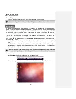
Страница 58: ...tform after the ground station system is opened To avoid loss of map data data backup software is provided in the Ubuntu operating system This software provides the following three functions 1 Save map data during use of the ground station the user can save the map data according to area partition and date Note The data backup file should not exceed the map capacity limit Google Earth 2G Google Ma...

Страница 59: ...hen go back to the Ubuntu system to open the Google Maps Data Management software Click Data Backup enter the backup name and click OK to save the last map data browsed in the ground station software See the following figure The system will pop up a dialog box indicating successful backup Generate backup data 3 Data Recovery Select the map data to be recovered the selected data are in orange backg...

Страница 60: ...Google Maps Data Management Click Exit at the top right corner of Google Maps Data Management software to exit the software c Log out of the Ubuntu system Click at the top right corner of the screen to select Shutdown Map backup editing is completed at this moment Auto Tracking Antenna The auto tracking antenna enables the user to accurately know the longitude and latitude information of the UAV p...

Страница 61: ...initialization is finished and blinks during normal working 6 Communication cable port 1 1 Receives video signals 2 Receives radio UART signals 3 The ground station sends commands via USB to the steering engine to control rotation of the antenna 7 Radio antenna extension cable port 1 Sends radio signals received to the ground station 8 Video antenna extension cable port 2 Sends video signals recei...

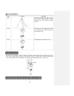
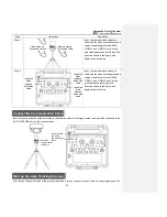
Страница 62: ...nto the PTZ groove in the direction of arrow Step 3 Tighten the knob on the left side to fix it Install the Antenna Use the wrench to install 4pcs of screw by aligning them with the corresponding holes in the panel antenna so as to fix it to the auto tracking antenna as shown in the figure below Then connect the 3pcs of antenna extension cable on the panel antenna to the auto tracking device accor...

Страница 63: ...ion according to the direction shown in the figure and tighten them clockwise Connect the Communication Cable Insert the communication cable according to the direction shown in the figure below and insert the other end to the AUTO ANTENNA port on the ground station Start up the Auto Tracking Antenna First turn on the power switch of the ground station then turn on the power switch of the auto trac...

Страница 64: ...o Files After startup the UAV will automatically enter the video recording state The user can preview the video on the screens of the remote control and the ground station When the UAV is shut down recording will be stopped and video files saved automatically Using a USB data cable you can copy the video files in the UAV to a PC for playback The real time videos sent back by the UAV can be saved t...

Страница 65: ... UAV fails to execute auto take off and one key auto fly Confirm whether the manual auto switch of the remote control or ground station is in auto state The UAV cannot be controlled manually when it goes home or lands upon low battery Make sure that the manual auto switch is switched 2 4 times when the throttle joystick is at the middle position The UAV inclines or rotates during one key auto fly ...

Страница 66: ...arefully before use and keep it handy for future reference Patented Technologies National Hi tech Enterprise Guangdong Famous Trademark Shenzhen Top Brand Popular in European American and Asian Markets with Self owned AEE Brand ...

Страница 67: ... determined by turning the equipment off and on the user is encouraged to try to correct the interference by one or more of the following measures Reorient or relocate the receiving antenna Increase the separation between the equipment and receiver Connect the equipment into an outlet on a circuit different from that to which the receiver is connected Consult the dealer or an experienced radio TV ...

Страница 68: ...Created in China Made in Shenzhen Add AEE Hi Tech Park Tangtou Intersection Songbai Road Shiyan Sub district Bao an District Shenzhen Tel 0755 29518999 Fax 0755 27358999 ...

Отзывы: