Screw Compressor Central Chiller
Chapter 3: Installation
26
Discharge Line Sizing
For horizontal runs, the discharge line should be pitched downward, in the direction of flow
at a rate of
¼
” for every 10 feet. This will allow oil to flow towards the condenser.
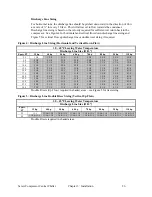
Discharge line sizing is based on the velocity required for sufficient oil return back to the
compressor. See Figure 4 for horizontal and vertical flow down discharge line sizing and
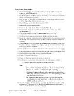
Figure 5 for vertical flow up discharge line or double riser sizing if required.
Figure 4: Discharge Line Sizing (Horizontal and Vertical Down Flow)
30 – 65°F Leaving Water Temperature
Discharge Line Size (O.D.”)
Equiv. FT
35 hp
40 hp
50 hp
60 hp
70 hp
80 hp
90 hp
110 hp
25
1 5/8
1 5/8
2 1/8
2 1/8
2 1/8
2 5/8
2 5/8
2 5/8
50
2 1/8
2 1/8
2 1/8
2 5/8
2 5/8
2 5/8
2 5/8
3 1/8
75
2 1/8
2 1/8
2 5/8
2 5/8
2 5/8
3 1/8
3 1/8
3 5/8
100
2 1/8
2 1/8
2 5/8
2 5/8
3 1/8
3 1/8
3 1/8
4 1/8
125
2 1/8
2 5/8
2 5/8
3 1/8
3 1/8
3 1/8
3 5/8
4 1/8
150
2 1/8
2 5/8
2 5/8
3 1/8
3 1/8
3 5/8
3 5/8
4 1/8
175
2 5/8
2 5/8
3 1/8
3 1/8
3 1/8
3 5/8
3 5/8
4 1/8
200
2 5/8
2 5/8
3 1/8
3 1/8
3 1/8
3 5/8
3 5/8
4 1/8
225
2 5/8
2 5/8
3 1/8
3 5/8
3 5/8
3 5/8
4 1/8
4 1/8
250
2 5/8
2 5/8
3 1/8
3 5/8
3 5/8
3 5/8
4 1/8
4 1/8
275
2 5/8
3 1/8
3 1/8
3 5/8
3 5/8
3 5/8
4 1/8
4 1/8
300
2 5/8
3 1/8
3 1/8
3 5/8
3 5/8
4 1/8
4 1/8
4 1/8
Double Risers (Up Flow) required in shaded areas – see Figure 5 for riser sizing
Figure 5: Discharge Line Double Riser Sizing (Vertical Up Flow)
30 – 65°F Leaving Water Temperature
Discharge Line Size (O.D.”)
Equiv.
FT
35 hp
40 hp
50 hp
60 hp
70 hp
80 hp
90 hp
110 hp
25
1 5/8
1 3/8 & 1 5/8
1 3/8 & 1 5/8
1 3/8 & 1 5/8
1 3/8 & 1 5/8
1 5/8 & 2 1/8
1 5/8 & 2 1/8
1 5/8 & 2 1/8
50
1 3/8 & 1 5/8
1 3/8 & 1 5/8
1 3/8 & 1 5/8
1 5/8 & 2 1/8
1 5/8 & 2 1/8
1 5/8 & 2 1/8
1 5/8 & 2 1/8
1 5/8 & 2 5/8
Double Risers required in shaded areas.

