Screw Compressor Central Chiller
Chapter 3: Installation
24
System Configuration
The system can be configured in any of the arrangements shown on page
XX
of the
Appendix. The configuration and distance between the chiller and the condenser affects pipe
size, refrigerant charge, oil return, and oil charge. Therefore, there are limitations that must
be adhered to for reliable and optimal operation.
x
Leaving water temperature affects discharge line size. Be sure to inform the installing
contractor of the leaving water temperature range in which the chiller will be
operating. The charts following are to cover any application within the full operating
range of the equipment. If the system is to be operated over a small range, it may be
possible for the installing contractor to determine a more economical piping
arrangement. The primary concern is to be sure that oil will be forced up the discharge
line to the condenser when the compressor is unloaded to minimum capacity
(approximately 30% of full capacity).
x
The total distance between the chiller and condenser should not exceed 200 feet or 300
equivalent pipe feet.
x
Refer to page
XX
of the Appendix for the location of traps.
x
Refrigeration lines must not be crossed, i.e., chiller liquid lines are to be piped to
condenser liquid lines.
x
HFC134A refrigerant and the ester based oil are extremely hygroscopic and will
absorb moisture from the ambient air very rapidly. It is imperative that the open time
on lines and components that are connected to the compressors are held to an absolute
minimum.
Sizing Refrigerant Lines
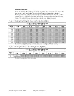
To determine field installed liquid and discharge line sizes, first establish the equivalent
length of pipe for each line, valve, and elbow. Chiller capacity and leaving water temperature
range are also required. See Figure 2 for lengths of refrigerant valves and fittings. Note that
short radius elbows should only be used for double riser bottom trap. Long radius elbows
should be used for all others.
Figure 2: Equivalent Length in Feet for Valves and Fittings
Line Size
Inches OD
Globe Valve
Equivalent Ft.
Angle Valve
Equivalent Ft.
Short Radius
Elbow
Equivalent Ft.
Long Radius
Elbow
Equivalent Ft.
Tee Straight
Through
Equivalent Ft.
7/8”
22
9
2.0
1.4
1.4
1 1/8”
29
12
2.6
1.7
1.7
1 3/8”
38
15
3.3
2.3
2.3
1 5/8”
43
18
4.0
2.6
2.6
2 1/8”
55
24
5.0
3.0
3.3
2 5/8”
69
29
6.0
4.1
4.1
3 1/8”
84
35
7.5
5.0
5.0
3 5/8”
100
41
9.0
5.9
5.9
4 1/8”
120
47
10.0
6.7
6.7

