background image


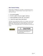
Dual Channel Hookup 

 
In Dual Mode, installation is very intuitive: input Channel 1 feeds 
output Channel 1, and input Channel 2 feeds output Channel 2. To 
activate Dual mode: 
 

1.  Turn off the amplifier  

2.  Wait 10 seconds for the power supply to discharge 

3.  Slide the Dual/Mono switch to the center position 

4.  Connect the output wiring as shown below.  

 
The high-current output block has three sets of output connectors per 
channel so multiple loads can be easily connected. Two sets accept 
banana plugs, while the third set accepts spade lugs or bare wire. 
Observe correct load polarity and be very careful not to short the two 
outputs.  


Page 19 

Содержание LVC 5050

Страница 1: ...tions 4 Specifications 5 Front Panel Functions 8 Back Panel Functions 9 Details of Plug In Mode 11 The CCIP Input Card 12 Installation 14 Unpacking 14 Mounting 15 Cooling 16 Making Connections 17 Dual Channel Hook up 18 Bridge Mono Hook up 20 Parallel Mono Hookup 21 Connecting Power 22 Page 1 ...

Страница 2: ...alling or operating the amplifier AE TECHRON is committed to continuous product improvement Technical progress may result in minor variations between this manual and a particular unit Any significant changes or customizations will be reflected in revisions of this manual Customers are encouraged to promptly add any additional information about their particular unit to this manual Page 2 ...

Страница 3: ...lifier is a highly sophisticated instrument Special hazard alert instructions appear throughout this guide Note the following examples NOTE A Note represents information which needs special emphasis but does not represent a hazard Page 3 ...

Страница 4: ...es an AMBER ON indicator Dual brightness indicator dim indicates signal presence bright indicates amplifier is in OVERLOAD Dual color RED and GREEN LED indicators show current limit and load current On the back panel Input is connected using bare wires Loads connect to a unique output block which combines heavy duty binding bolts and dual banana connectors A detachable cover on the output block pr...

Страница 5: ... kHz at 1 watt Phase Response 10 from 10 Hz to 20 kHz at 1 watt Signal to Noise Ratio At 26 dB gain better than 105 dB A weighted below full output Total Harmonic Distortion THD 0 05 from 20 Hz to 1 kHz increasing linearly to 0 1 at 20 kHz at full output I M Distortion 0 05 from 410 milliwatts to full output at 26 dB gain with an 8 ohm load Slew Rate 30 V per microsecond Load Impedance Rated for 1...

Страница 6: ...low voltage under ODEP conditions Indicators Amber Enable Indicator shows on off status of low voltage power supply A Green OVERLOAD indicator for each channel flashes dim green to show a signal is present at the input and flashes brightly in the rare event distortion of any kind exceeds 0 05 including input overload A bi color Green Red ILOAD ILIMIT indicator for each channel flashes green with t...

Страница 7: ...steel chassis with specially designed flow through front to rear ventilation system with computer controlled forced air cooling Dimensions 19 inch 48 3 cm wide 5 25 inch 13 3 cm high 16 inch 40 3 cm deep behind front mounting surface and 2 875 inches 7 3 cm in front of the mounting surface NOTE Allow 4 inches in back for adequate airflow Weight 77 lbs 35 2 kg net 88 lbs 40 2 kg shipping weight Mou...

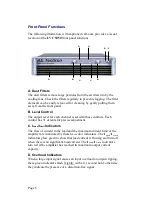
Страница 8: ...ontrol has 31 detents for precise adjustment C ILoad ILimit Indicators The flow of current to the load and the maximum current limit of the amplifier are monitored by these two color indicators The I Load I Limit indicators glow green to show that load current is flowing and turn off when there is no significant load current The I Load I Limit indicators turn red if the amplifier has reached its m...

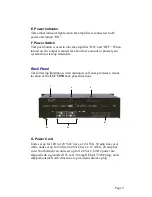
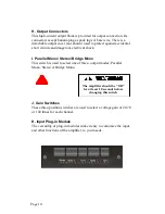
Страница 9: ...ansients G H I J J K Back Panel The following illustration with captioned call outs provides a visual location of the LVC 5050 back panel functions G Power Cord Units set up for 100 to 120 VAC have a 10 AWG 30 amp line cord while units set up for 200 to 240 VAC have a 12 AWG 20 amp line cord North American units set up for 120 VAC 60 Hz power are shipped with a grounded 125 volt 30 amp NEMA TT30P ...

Страница 10: ...arallel Mono Stereo Bridge Mono This switch is used to select one of three output modes Parallel Mono Stereo or Bridge Mono J Gain Switches These three position switches are used to select a voltage gain of 20 70 or 140 times for each channel K Input Plug in Module The versatility of plug in modules make it easy to customize the input and other functions of the amplifier to your needs The amplifie...

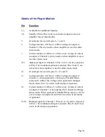
Страница 11: ...lanced input is desired Pins 9 and 11 are not active when amplifier is used in either mono mode 12 Ground pin for use with pins 13 14 and 15 13 Voltage monitor will have 1 20th of voltage at output of Channel 1 when operated in 2 channel or Parallel Mono mode and 1 40th of the voltage when operated in Bridged Mono mode Pin 13 is active in all modes of operation 14 Current monitor will have 1 volt ...

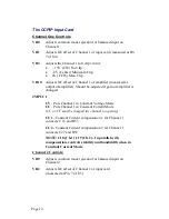
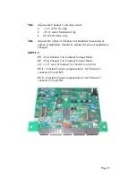
Страница 12: ...of amplifier is changed JMPCC1 CV Puts Channel 1 in Constant Voltage Mode CC Puts Channel 1 in Constant Current Mode CC or CV must be jumped for channel to operate CC1 Constant Current compensation 1 for Channel 1 connects C 23 and R55 CC2 Constant Current compensation 2 for Channel 1 connects C27 and R59 NOTE C18 Ch 1 C19 Ch 2 In parallel with compensation controls stability and bandwidth when in...

Страница 13: ...ured at output of amplifier Should be adjusted if gain of amplifier is changed JMPCC2 CV Puts Channel 2 in Constant Voltage Mode CC Puts Channel 2 in Constant Current Mode CC or CV must be jumped for channel to operate CC1 Constant Current compensation 1 for Channel 2 connects C24 and R53 CC2 Constant Current compensation 2 for Channel 2 connects C26 and R61 ...

Страница 14: ...Make written notes of any damage for future reference b If damage is found notify the transportation company immediately c Save the shipping carton and packing materials as evidence of damage for the shipper s inspection d If severe damage is apparent DO NOT proceed until a representative of the shipping company is present 2 Uncrate unpack the amplifier 3 Save the packing materials for later use i...

Страница 15: ... cm rack mounting and stack mounting without a cabinet For optimum cooling and rack support multiple units should be stacked directly on top of each other To reduce the risk of ELECTRIC SHOCK or FIRE HAZARD DO NOT expose the LVC5050 to rain or moisture Page 15 ...

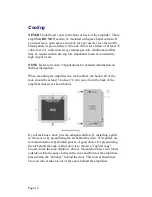
Страница 16: ...issipation When mounting the amplifier in a rack cabinet the back wall of the rack should be at least 3 inches 7 6 cm away from the back of the amplifier chassis as shown below If your rack has a door provide adequate airflow by installing a grille in the door or by pressurizing the air behind the door Wire grilles are recommended over perforated panels A good choice for pressurizing the air behin...

Страница 17: ...h to carry the intended current to the load 3 Use good quality connectors with proper strain relief Do not use connectors that have any tendency to short circuit Do not use connectors that can be plugged into AC power receptacles 4 Keep unbalanced input cables as short as possible Avoid lengths greater than 10 feet 5 Do not run signal input cables together with high level wiring such as load outpu...

Страница 18: ...y or power main These connections will cause serious damage to the amplifier 9 Do not permit unqualified personnel to tamper with circuitry Do not make unauthorized circuit modifications Serious damage to the amplifier and or safety hazards may result Page 18 ...

Страница 19: ...r the power supply to discharge 3 Slide the Dual Mono switch to the center position 4 Connect the output wiring as shown below The high current output block has three sets of output connectors per channel so multiple loads can be easily connected Two sets accept banana plugs while the third set accepts spade lugs or bare wire Observe correct load polarity and be very careful not to short the two o...

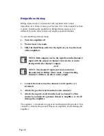
Страница 20: ... from the channel 1 input with the output of channel 2 inverted so it can be bridged with the channel 1 output AND NOTE The channel 2 input and level control are disconnected in Bridge Mono mode A signal feeding channel 2 will have no effect on the output 1 Connect the load across the channel 1 and 2 positive terminals 2 Attach the positive lead from the load to channel 1 3 Attach the negative lea...

Страница 21: ...eceive the signal from the channel 1 input NOTE The channel 2 input and level control are disconnected in Parallel Mono mode A signal feeding channel 2 will have no effect on the output To complete connections 1 Install a jumper wire between the positive outputs of channel 1 and 2 that is at least 14 gauge in size 2 Connect the load to the output of channel 1 as shown below 3 Connect positive lead...

Страница 22: ...d without a plug Whenever possible connect the power cord to an isolated power circuit with adequate current Excessive line voltages of more than 11 above the amplifier s rated line voltage will activate the overvoltage protection circuitry All specifications in this manual were measured using 120 VAC 60 Hz power mains unless otherwise noted Specifications are derived using a peak main voltage equ...

Страница 23: ...Notes Page 23 ...

Страница 24: ...Notes Page 24 ...

Отзывы: