17
SOM-3569 User Manual
Chapter 2
M
echanical
Information
2.3
Assembly Drawing
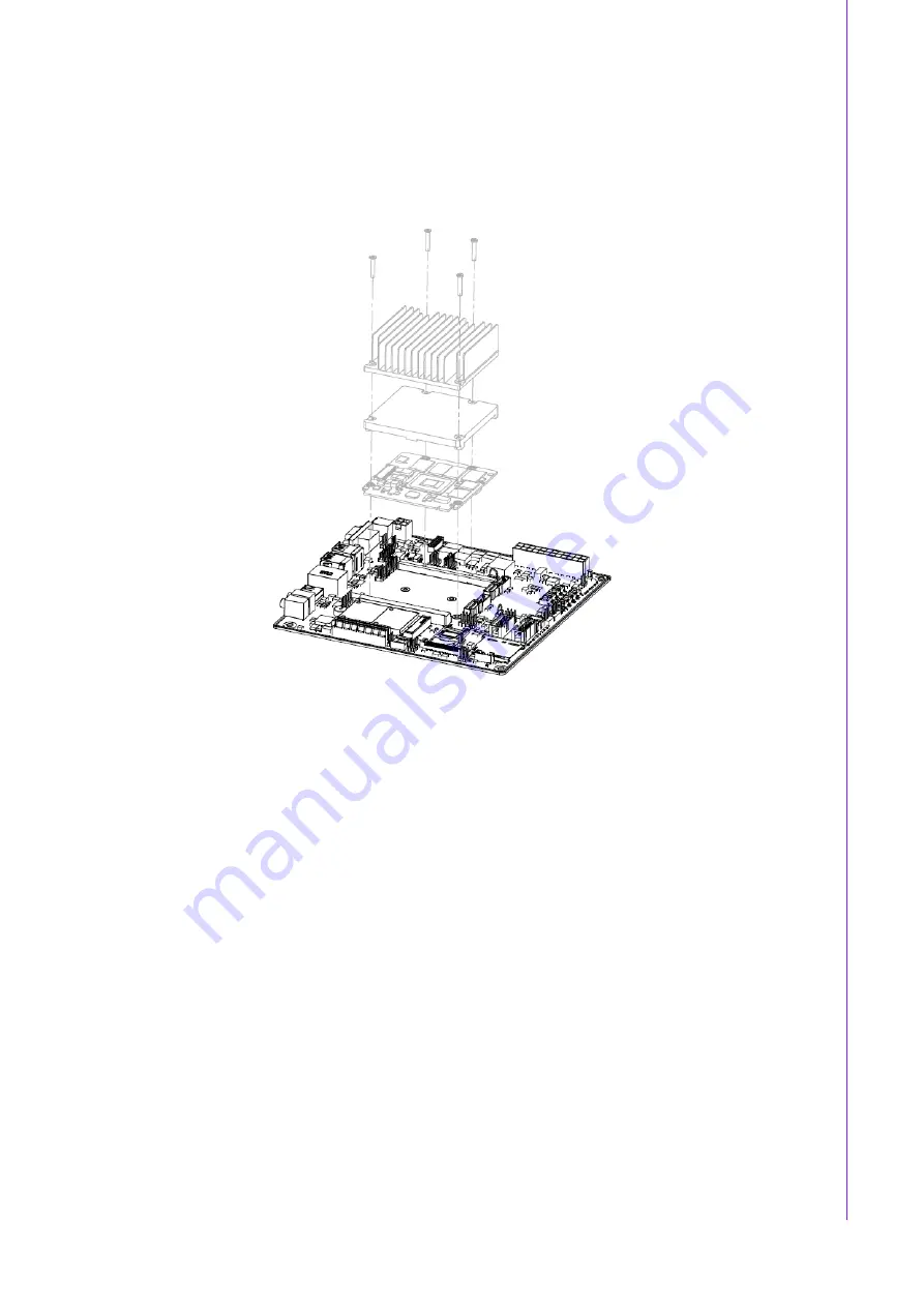
These figures demonstrate the assembly order from the thermal module and COM
module to the carrier board.
Figure 2.6 Assembly Drawing
There are 4 reserved screw holes for SOM-3569 to be pre-assembled with the heat
spreader.
Содержание SOM-3569
Страница 1: ......
Страница 3: ...User Manual SOM 3569...
Страница 12: ...SOM 3569 User Manual x...
Страница 24: ...SOM 3569 User Manual 12...
Страница 28: ...SOM 3569 User Manual 16 Figure 2 5 Board Mechanical Drawing Side...
Страница 70: ...SOM 3569 User Manual 58...
Страница 71: ...Chapter 4 4 S W Introduction Installation S W Introduction Driver Installation Advantech iManager...
Страница 73: ...61 SOM 3569 User Manual Chapter 4 S W Introduction Installation...
Страница 74: ...SOM 3569 User Manual 62...


