background image

Chapter 3 Jumper Setting and Connectors. 


3.1 Jumpers


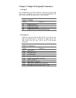
The motherboard of the PPC-L60T has a number of jumpers that 
allow you to configure your system to suit  your  application. The 
table below lists the functions of the various jumpers. 


Table 3.1: Jumpers


Label Function 


S1 

Panel type select 


S2 CMOS 

clear 

button 


S3 System 

reset 

button 


JP1 

COM2 RS232/422/485 & WDT setting 


3.2 Connectors


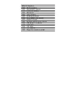
On-board connectors link the PPC-L60T to external devices 
such as hard disk drives,  a keyboard, or  floppy drives.  The 
table below  lists  the func- tion  of each of the board’s 
connectors. 


Table 3.2: Connectors


Label Function 

CN1 ATX 

feature 


CN2 CPU 

fan 

power 


CN3 Ext. 

flat 

panel 


CN4 

Flat panel connector 


CN5 

LCD Inverter control connector 


CN6 LVDS 

connector 


CN7 Main 

Power 

connector 


CN8 ATX 

power 

on/off 

switch 

connector 


CN9 

Peripheral power connector (-5V, -12V)

Содержание PPC-L60T

Страница 1: ...IA Eden Processor based Fanless Panel PC with 6 4 TFT LCD Contents Chapter 1 General information Chapter 2 System Setup Chapter 3 Jumper Setting and Connectors Chapter 4 Hardware Installation and Upgr...

Страница 2: ...er friendly as a multi function computer For system integrators this simple complete compact and high integrated multimedia system lets you easily build a panel PC into your application Common industr...

Страница 3: ...N 133T Chipset z Front Side bus 133 MHz z 2nd level cache 64 KB on the Eden processor z System Memory One 144 pin SODIMM socket up to 512 MB SDRAM z Series ports Two serial ports with two 232 ports on...

Страница 4: ...nuous Light Transmission 80 Controller USB interface Software Driver Support Windows 98 2000 XP Durability 10million Touch in a lifetime Optional modules Memory up to 512 MB SDRAM Standard is built in...

Страница 5: ...cd m2 z Temperature 50 C z Backlight Lifetime 20 000hrs Note The color LCD display installed in the Panel PC is high quality and reliable However it may contain a few defective pixls which don t alwa...

Страница 6: ...ors and ports which are illustrated in the figures as below When you place the Panel PC upright on the desktop its front panel appears as shown in the Figure 2 1 When you turn the panel PC around and...

Страница 7: ...Switch on the power Switch on the power switch on the rear cover 2 3 Running the BIOS setup program Your Panel PC is likely to have been the properly set up and configured by your dealer prior to deli...

Страница 8: ...de setup program which automatically load and guide you through hard disk preparation and operating system installation The guidelines below will help you determine the steps necessary to install your...

Страница 9: ...The various drivers and utilities in the CD ROM disc have their own test files which help users install drivers and understand their functions These files are a very useful supplement to the informati...

Страница 10: ...m reset button JP1 COM2 RS232 422 485 WDT setting 3 2 Connectors On board connectors link the PPC L60T to external devices such as hard disk drives a keyboard or floppy drives The table below lists th...

Страница 11: ...onnector CN13 IR connector CN14 Audio connector CN15 Parallel port connector CN16 Power HDD LED connector CN17 Ethernet connector CN18 Keyboard and PS 2 mouse connector CN19 USB channel 1 2 connector...

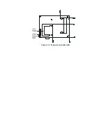
Страница 12: ...3 3 Locating jumpers Figure 3 1 Jumper locations...

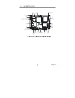
Страница 13: ...3 4 Locating Connectors Figure 3 2 Connectors component side 11 Chapter 2...

Страница 14: ...Figure 3 3 Connectors solder side...

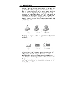
Страница 15: ...mper you remove the clip Sometimes a jumper will have three pins labeled 1 2 and 3 In this case you would connect either pins 1 and 2 or 2 and 3 open closed closed 2 3 The jumper settings are schemati...

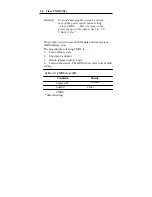
Страница 16: ...ck to 3 0 V Battery On This jumper is used to erase CMOS data and reset system BIOS informa tion The procedure for clearing CMOS is 1 Turn off the system 2 Short pin 2 and pin 3 3 Return jumper to pin...

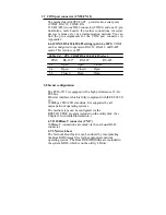
Страница 17: ...Open Closed 3 4 Open Closed Open 5 6 Closed Open Open 3 8 hernet configuration The PCM 9373 is equipped with a high performance 32 bit PCI bus Ethernet interface which is fully compliant with IEEE 80...

Страница 18: ...setting JP1 as shown below Table 2 6 JP1 Watchdog timer action Pins System reset IRQ11 7 8 closed open 9 10 open closed Default setting 3 10 USB connectors CN19 The PCM 9373 board provides up to four...

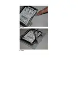
Страница 19: ...e Panel PC you should be aware of this 4 2 Installing the 2 5 Hard Disk Drive HDD You can attach one enhanced Integrated Device Electronics IDE Hard disk drive to the panel PC S internal controller wh...

Страница 20: ...Fig 4 1 Fig 4 2...

Страница 21: ...Fig 4 3 Fig 4 4...

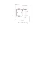
Страница 22: ...nto a panel Panel Mounting can help system integrators conveniently integrate the Panel PC in their system To construct a suitable panel refer the following cutout dimensions diagram Note The panel th...

Страница 23: ...Insert the screws from the front side into the holes and tighten them with the nuts provided See Figure E 2 3 The screw size is M3 L L wall thickness 5 0mm 2 Clamper Mount 1 There are four holes locat...

Страница 24: ...Figure 5 2 Panel Mounting...

Страница 25: ...Figure 5 3 Panel Mounting 5 1 3 Cut out area Refer to Figure 5 3 below for the locations and dimensions for the cut out area and mounting holes...

Страница 26: ...Figure 5 3 Dimension of Panel mounting holes...

Страница 27: ......

Отзывы: