POC-S176 User Manual
8
2.1
A Quick Tour of the POC-S176
Before you start to set up the POC-S176, take a moment to become familiar with the
locations and purposes of the controls, drives, connections and ports, which are illus-
trated in the figures below.
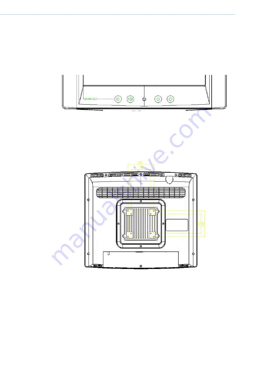
When you place the POC-S176 upright on the desktop, its front panel appears as
shown in Figure 2.1.
Figure 2.1 Front view of the Point-of-care terminal
When you turn the Point-of-Care Terminal around and look at its rear cover, the
sunken I/O section is at the bottom of the panel PC, as shown in Figure 2-2. (The I/O
section includes various I/O ports, including serial ports, DVI port, the Ethernet port,
USB ports, the DC power adapter jack, and so on.)
Figure 2.2 Rear view of the Point-of-Care Terminal
Содержание POC-S176 Series
Страница 1: ...User Manual POC S176 Point of Care Terminal ...
Страница 8: ...POC S176 User Manual viii ...
Страница 11: ...Chapter 1 1 General Information Sections include Introduction Specifications LCD Specifications Dimensions ...
Страница 22: ...POC S176 User Manual 12 ...
Страница 23: ...Chapter 3 3 Chipset and Graphics Setup Sections include Introduction Installation of Chipset Driver ...
Страница 31: ...Chapter 4 4 Audio Interface Sections include Introduction Installation of Audio Driver Further Information ...
Страница 38: ...POC S176 User Manual 28 ...
Страница 51: ...Appendix A A Description of Connectors ...
Страница 55: ...Appendix B B Windows Display Hot Key Function ...
Страница 57: ...47 POC S176 User Manual Appendix B Windows Display Hot Key Function ...


