POC-621 Series User Manual
14
2.1
A Quick Tour of the POC-621 Series
Before you start to set up the POC-621 take a moment to become familiar with the
locations and purposes of the controls, drives, connection, and ports. These are illus
-
trated in the figures below.
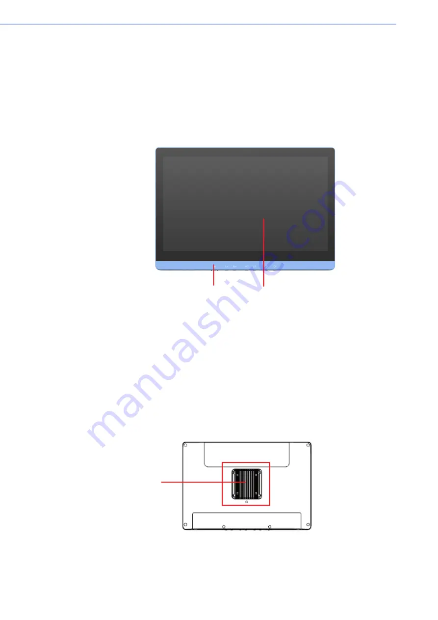
When you place the POC-621 Series upright on the desktop, its front panel appears
as shown in the following figure — Figure 2.1.
2.1.1
Front view
Figure 2.1 Front View of the Point-of-Care Terminal
Front Bezel view
(1)
LCD panel with Touch Screen module
(2)
Power symbol w/ indicator light
2.1.2
Rear View
When you turn the Point of Care Terminal around and look at its rear cover, the
sunken I/O section can be found at the bottom of the panel PC, as shown in Figures
2.2 and 2.3. (The I/O section includes various I/O ports — like serial ports, a VGA
port, an Ethernet port, USB ports, etc.)
Figure 2.2 Rear View of the Point of Care Terminal
(1)
(2)
(1)
Содержание POC-621 Series
Страница 1: ...User Manual POC 621 Series DC AC in model 21 Computer...
Страница 15: ...Chapter 1 1 General Information...
Страница 25: ...11 POC 621 Series User Manual Chapter 1 General Information...
Страница 26: ...POC 621 Series User Manual 12...
Страница 27: ...Chapter 2 2 System Setup...
Страница 40: ...POC 621 Series User Manual 26...
Страница 41: ...Chapter 3 3 Hot Swapping Battery Pack Operation...
Страница 48: ...POC 621 Series User Manual 34...
Страница 49: ...Chapter 4 4 Operation and Safety...
Страница 60: ...POC 621 Series User Manual 46...
Страница 61: ...Appendix A A POC 621 Series VESA Mounting...
Страница 63: ...Appendix B B Driver Installation...
Страница 65: ...Appendix C C PCM 8722 Connector Map...
Страница 66: ...POC 621 Series User Manual 52 C 1 PCM 8722 Connector Map...
Страница 67: ...53 POC 621 Series User Manual Appendix C PCM 8722 Connector Map...
Страница 68: ...POC 621 Series User Manual 54...
Страница 69: ...Appendix D D PCM 8722 Jumper Settings...
Страница 75: ...Appendix E E Advanced BIOS Functions...


