background image

Chapter 4  FPM Receiver Setup (PanelLink) (for PCA-6654 only)

55

8.

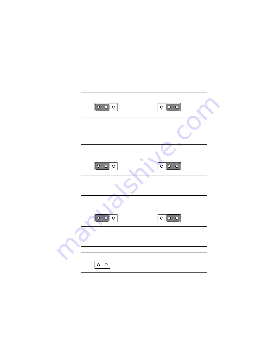
Set J8 as follows:

Table 4-24: LCD signal level select (J8)

* 5 V

3.3 V

* default setting

9.

You do not need to set J13.

10. Set J14 as follows:

Table 4-25: LCD input clock select (J14)

* Divided by one

Divided by two

* default setting

11. Set J15 as follows:

Table 4-26: Backlight level select (J15)

* ENAV

EE

 [high level]

/ENAV

EE

 [low level]

* default setting

12. Set J16 as follows:

Table 4-27: Power down select (J16)

Normal

1

1

1

1

1

1

Содержание PCA-6654

Страница 1: ...PCA 6654 6654L Video Display Card for Flat Panel and CRT ...

Страница 2: ...vantech Co Ltd Information provided in this manual is intended to be accurate and reliable However Advantech Co Ltd assumes no responsibility for its use nor for any infringements upon the rights of third parties which may result from its use All brand and product names mentioned herein are trademarks or registered trademarks of their respective holders Warning Do not set V H SYNC Blank in the Awa...

Страница 3: ...PCA 6654 6654L card PCA 6654 6654L User s Manual PCA 6654 6654L installation driver Introduction PCA 6654 This is the standard version of the video display card It contains PanelLink features which enables it to be used with Advantech s FPM receiver series including the FPM 37 and FPM 40 PCA 6654L This is the localized version of the video display card It does not contain PanelLink features It has...

Страница 4: ...iv PCA 6654 Board Layout PCA 6654L Board Layout ...

Страница 5: ...istributor sales representative or Advantech s customer service center for technical support if you need additional assistance Please have the following information ready Product name and serial number Description of your peripheral attachments Description of your software operating system version application software etc Complete description of the problem Exact wording of any error messages ...

Страница 6: ...sed for a long time disconnect it from the power source to avoid damage by transient over voltage 12 Never pour any liquid into an opening This could cause fire or electrical shock 13 Never open the equipment For safety reasons the equipment should be opened only by qualified service personnel 14 If any of the following situations arises get the equipment checked by service personnel a The power c...

Страница 7: ...n längeren Zeitraum nicht benutzt sollten Sie es vom Stromnetz trennen Somit wird im Falle einer Überspannung eine Beschädigung vermieden 12 Durch die Lüftungsöffnungen dürfen niemals Gegenstände oder Flüssigkeiten in das Gerät gelangen Dies könnte einen Brand bzw elektrischen Schlag auslösen 13 Öffnen Sie niemals das Gerät Das Gerät darf aus Gründen der elektrischen Sicherheit nur von authorisier...

Страница 8: ... Connectors for Adjuster 10 J4 10 J5 10 J9 10 2 5 Board Layout Jumpers Connectors and Switches 10 2 6 Jumper and Switch Settings 12 2 6 1 LCD signal level select J6 12 2 6 2 LCD bias voltage select MONO J7 12 2 6 3 LCD bias voltage select J8 13 2 6 4 LCD type select SW1 13 2 6 5 LCD clock configuration select for PanelLink only SW2 14 2 6 6 LCD control signal configuration select for PanelLink onl...

Страница 9: ...r Adjuster 40 J1 40 J2 40 J7 40 4 5 Board Layout Connectors 41 4 6 Jumpers and Switches 42 4 7 Board Layout Jumpers and Switches 43 4 8 Jumper and Switch Settings 44 4 8 1 LCD bias voltage select J5 44 4 8 2 LCD signal level select J8 44 4 8 3 LCD bias voltage select MONO J13 45 4 8 4 LCD input clock select J14 45 4 8 5 Backlight level select J15 45 4 8 6 Power down select J16 46 4 8 7 LCD type se...

Страница 10: ...ower Connector J10 67 Appendix B Pin Assignments FPM Receiver PanelLink 69 B 1 Flat Cable Panel Display Header JP3 70 B 2 Flat Cable Panel Display Extension Header JP4 71 B 3 Backlight Power J3 71 B 4 Extension Power J6 71 B 5 Flat Panel Display J10 72 B 6 FFC Connector A For Flat Panel Display J11 73 B 7 FFC Connector B For Flat Panel Display J12 74 B 8 Keyboard Connector J17 74 ...

Страница 11: ...Introduction Description Specifications Driver Support Utility Support Video BIOS Simultaneous Display Mode 1 C HAPTER ...

Страница 12: ...dard modes The enclosed software drivers allow you to take advantage of the extended features of the PCA 6654 6654L High performance in Microsoft Windows Resolutions up to 1024 x 768 in graphics modes with 64 K colors 640 x 480 resolution in graphics modes with 32K 64K and 16M colors 132 column text mode Warning Be sure to turn off the power and unplug all components before attempting to install o...

Страница 13: ... by 4 colors 128 x 128 pixels by 2 colors Simultaneous CRT LCD display Available with TFT DSTN MONO and CRT Display support Display centering and stretching features for optimal fit of VGA graphics and text on 800 x 600 and 1024 x 768 panels CRT Up to 1024 x 768 non interlaced analog or multi synch monitors with 64 K colors Flat panel TFT LCD Max resolution 1024 x 768 up to 64 K colors DSTN LCD Ma...

Страница 14: ...ightness Power On board DC DC converter supplies LCD bias voltage LCD backlight power supplied PanelLink High speed and low EMI operation Flexible panel interface 1 3 Driver Support The software driver provides for the following systems Software Name of VGA Driver Disk Microsoft Windows 95 PCA 6654 VGA Driver Windows 95 NT 4 0 Microsoft Windows NT 4 0 PCA 6654 VGA Driver Windows 95 NT 4 0 IBM OS 2...

Страница 15: ...d can only be used for testing 1 5 Video BIOS The standard BIOS chip supports eight kinds of flat panel displays 1024 x 768 DSTN Sharp LM14X82 640 x 480 MONO Sharp LM64P89 640 x 480 DSTN Kyocera KCB6448BSTT X5 800 x 600 DSTN 640 x 480 SHARP TFT 640 x 480 18 bit TFT Toshiba LTM10C209A 1024 x 768 TFT 800 x 600 TFT Toshiba LTM10C273 Note 1 To program the VGA BIOS to support the LCD only you must use ...

Страница 16: ... display to a CRT monitor and a flat panel display The flat panel may be TFT DSTN or MONO If you use a DSTN LCD in this mode the display must be under 16 256 colors or the CRT and flat panel screens will tremble You must add a frame buffer with 512 K RAM and update the BIOS setup Call us for assistance ...

Страница 17: ...ation Jumpers and Connectors Jumpers Connectors and Switches Connectors for Adjuster Board Layout Jumpers Connectors and Switches Jumper and Switch Settings LCD Setup Preliminary TFT LCD Setup DSTN LCD Setup MONO LCD Setup 2 C HAPTER ...

Страница 18: ...emory 512KB Frame Buffer BIOS C R T Display Power on sequencing DC DC Converter Flat Panel Display Panel Link Transmitter SiI 100 140 Panel Link Receiver SiI 101 141 Address Data Control Address Data Address Data Address Data 32 Bit PCI Bus RGB H V Sync DDC CLK Data ENAVEE ENAVDD Panel Data Panel Control V D D S A F E V E E S A F E Flat Panel Display Data Pairs CLK Pair Data Control LCD Monitor 32...

Страница 19: ...er will have three pins labeled 1 2 and 3 In this case you would connect either pins 1 and 2 or pins 2 and 3 The jumper settings are schematically depicted in this manual as follows A pair of needle nose pliers may be helpful when working with jumpers If you have any doubts about the best hardware configuration for your application contact your local distributor or sales representative before you ...

Страница 20: ...s voltage select MONO J8 LCD bias voltage select SW1 LCD type select SW2 LCD clock configuration select for PanelLink only SW3 LCD control signal configuration select for PanelLink only Please refer to Appendix A for pin assignments 2 4 Connectors for Adjuster J4 This is a 3 pin housing Connect a 500 Ω external VR to adjust VCON voltage range 0 2 8 V J5 This is a 2 pin housing Connect a 500 Ω exte...

Страница 21: ...lat panel display J3 Keyboard connector CN1 CRT display SW3 LCD control signal configuration select J7 LCD bias voltage select MONO J5 MONO LCD contrast adjustment J6 LCD signal level select J9 LCD brightness adjustment JP1 Flat panel display header SW1 LCD type select SW2 LCD clock configuration select J4 DSTN LCD contrast adjustment J10 Backlight power connector ...

Страница 22: ...per and switch locations For information about installing an LCD into your system refer to Section 2 LCD Setup or Chapter 4 FPM Receiver Setup of this manual 2 6 1 LCD signal level select J6 Table 4 4 LCD signal level select J6 5 V 3 3 V default setting 2 6 2 LCD bias voltage select MONO J7 Table 4 5 LCD bias voltage select MONO J7 VEE 5 V 40 V VEE 0 V 40 V default setting 1 1 1 1 ...

Страница 23: ...fault setting 2 6 4 LCD type select SW1 Table 2 5 LCD type select SW1 LCD type Pin 1 Pin 2 Pin 3 Pin 4 640 x 480 18 bit TFT OFF ON OFF ON 640 x 480 SHARP TFT ON ON OFF ON 800 x 600 TFT OFF OFF OFF ON 1024 x 768 TFT ON OFF OFF ON 640 x 480 DSTN ON OFF ON ON 800 x 600 DSTN OFF OFF ON ON 1024 x 768 DSTN ON ON ON ON 640 x 480 MONO OFF ON ON ON default setting 1 1 ...

Страница 24: ...D control signal configuration select for PanelLink only SW3 Table 2 7 LCD control signal configuration select for PanelLink only SW3 Pin number and setting details 1 The LCD input data are latched on falling edge of clock ON The LCD input data are latched on rising edge of clock OFF 2 The LCD control signals are latched on falling edge of clock ON The LCD control signals are latched on rising edg...

Страница 25: ... bias voltage for DSTN or MONO Vmin Vtyp Vmax 5 Backlight brightness voltage range in inverter You must also have the following parts ready 1 LCD cable to connect the LCD to JP1 2 Inverter which must match your LCD specifications 3 Inverter power wire to connect the inverter to J10 4 500 Ω VR assembly with wire for adjusting brightness 5 500 Ω VR assembly with wire for adjusting contrast DSTN or M...

Страница 26: ...etting 2 Set SW2 as follows for all TFT LCDs LCD type Pin 1 Pin 2 Pin 3 Pin 4 All TFT types ON OFF ON OFF 3 You do not need to set SW3 4 Set J6 according to your LCD input power specifications Table 2 9 LCD signal level select J6 5 V 3 3 V default setting 5 You do not need to set J7 or J8 6 Connect the LCD cable inverter inverter power wire and VR assembly with wire to J9 See Fig 2 3 7 Plug the VG...

Страница 27: ...Chapter 2 Hardware Setup 17 Figure 2 3 TFT LCD setup Brightness VR LCD cable Inverter power wire PCA 6654 6654L Inverter ...

Страница 28: ... 640 x 480 DSTN ON OFF ON ON 800 x 600 DSTN OFF OFF ON ON 1024 x 768 DSTN ON ON ON ON 2 Set SW2 as follows for all DSTN LCDs LCD type Pin 1 Pin 2 Pin 3 Pin 4 All DSTN types ON OFF ON OFF 3 You do not need to set SW3 4 Set J6 according to your LCD input power specifications Table 2 11 LCD signal level select J6 5 V 3 3 V default setting 5 You do not need to set J7 1 1 2 3 1 2 3 ...

Страница 29: ...ter inverter power wire and VR assembly The VR assembly with wire for brightness control should be connected to J9 and the wire for contrast control should be connected to J4 See Fig 2 4 8 Plug the VGA card into the PCI slot 9 Power on the system 10 Adjust the screen brightness and contrast using the VR controls 1 1 2 3 ...

Страница 30: ...20 PCA 6654 6654L User s Manual Figure 2 4 DSTN LCD setup Brightness VR LCD cable Inverter power wire PCA 6654 6654L Inverter Contrast VR ...

Страница 31: ... ON ON ON 2 Set SW2 as follows LCD type Pin 1 Pin 2 Pin 3 Pin 4 640 x 480 MONO ON OFF ON OFF 3 You do not need to set SW3 4 Set J6 according to your LCD input power specifications Table 2 13 LCD signal level select J6 5 V 3 3 V default setting 5 Set J7 as follows Table 2 14 LCD bias voltage select MONO J7 VEE VEE 1 2 3 1 1 2 3 1 2 3 1 1 2 3 ...

Страница 32: ...3 to be VEE max 11 Power off the system 12 Remove the jumper on J5 13 Connect the LCD cable inverter inverter power wire and VR assembly The VR assembly with wire for brightness control should be connected to J9 and the wire for contrast control should be connected to J5 See Fig 2 5 14 Power on the system 15 Adjust the screen brightness and contrast using the VR controls 1 2 3 ...

Страница 33: ...Chapter 2 Hardware Setup 23 Figure 2 5 MONO LCD setup Brightness VR LCD cable Inverter power wire PCA 6654 6654L Inverter Contrast VR ...

Страница 34: ...24 PCA 6654 6654L User s Manual ...

Страница 35: ...ration of the software drivers on the display driver diskettes included in your PCA 6654 6654L package Sections in this chapter include Simultaneous Display Mode Installation for Windows 95 Installation for Windows NT Installation for OS 2 Further Information 3 C HAPTER ...

Страница 36: ...T supported Multiple frequency multisync monitors are supported as analog monitors Both CRT and panel displays can be used simultaneously The PCA 6654 6654L can be set in one of three configurations on a CRT on a flat panel display or on both simultaneously The system is initially set to simultaneous display mode In the utility diskettes there are three COM files which can be used to select the di...

Страница 37: ...l Panel b Double click the display icon c Choose the Settings label d Press the Advanced Properties button a Choose the Adapter label b Press the Change button a Press the Have Disk button a Insert the VGA Driver Windows 95 NT 4 0 disk into the floppy driver b Type A WIN95P 244 c Press the OK button 1 2 3 4 ...

Страница 38: ...nd Tech 65550PCI appear in the Adapter label b Press the Close button a Press the Yes button b Close all windows to reboot a Repeat Step 1 on the previous page of this manual b The Chips label appears in Display Properties c Adjust the resolution and color 5 6 7 8 ...

Страница 39: ...ivers and Utilities 29 a Choose the Chips label b Adjust the refresh rate and display device c Press the OK button a Press the OK button to change the display setting a Press the OK button to confirm the setting END 9 10 11 ...

Страница 40: ...button a Press the Have Disk button a Insert the VGA Driver Windows 95 NT 4 0 disk into the floppy driver b Type A WINNT4 115 c Press the OK button a Select Start Settings Control Panel b Double click the display icon c Choose the Settings label d Press the Display Type button 1 2 3 4 ...

Страница 41: ...ss the OK button b Close all windows to reboot a Repeat Step 1 on the previous page of this manual b The Chips label appears in Display Properties c Adjust the resolution color and refresh rate d Press the Test button to check the setting e Press the OK button to confirm the setting END 5 6 7 8 ...

Страница 42: ...rt the VGA Driver OS 2 disk into the floppy driver c Type A Enter d Type setup A C Enter a Press the OK button to shut down b Reboot again a Select OS 2 System System Setup Display Driver Install b Enable Primary Display c Press the OK button a Select Chips Technologies 65550 554 555 b Press the OK button 1 2 3 4 ...

Страница 43: ...elect Install Using Defaults for Monitor Type b Press the OK button a Type A b Press the Install button a Insert the VGA Driver OS 2 disk into the floppy driver b Press the OK button a Press the OK button to shut down and restart the system 5 6 7 8 ...

Страница 44: ...34 PCA 6654 6654L User s Manual a Select OS 2 System System Setup System a Select the Screen tab b Adjust the resolution color and refresh rate END 9 10 ...

Страница 45: ...ion For further information about installation of the PCI SVGA in your PCA 6654 6654L including driver updates troubleshooting guides and FAQ lists visit the following web resources C Twebsite www chips com Advantech web sites www advantech com www advantech com tw ...

Страница 46: ...36 PCA 6654 6654L User s Manual ...

Страница 47: ...troduction Jumpers and Connectors Connectors Connectors for Adjuster Board Layout Connectors Jumpers and Switches Board Layout Jumpers and Switches Jumper and Switch Settings LCD Setup Preliminary TFT LCD Setup DSTN LCD Setup MONO LCD Setup 4 C HAPTER ...

Страница 48: ... high speed data transmission over the same interface from VGA to SVGA resolutions and up to HDTV resolution in the future The PanelLink transmitter incorporates an advanced coding scheme to enable TMDS signals to reduce EMI across copper cables and DC balancing for data transmission over fiber optics In addition the advanced coding scheme enables robust clock recovery at the receiver to achieve h...

Страница 49: ...metimes a jumper will have three pins labeled 1 2 and 3 In this case you would connect either pins 1 and 2 or pins 2 and 3 The jumper settings are schematically depicted in this manual as follows A pair of needle nose pliers may be helpful when working with jumpers If you have any doubts about the best hardware configuration for your application contact your local distributor or sales representati...

Страница 50: ...anel display J17 Keyboard connector J1 MONO LCD contrast adjustment J2 Brightness adjustment J7 DSTN LCD contrast adjustment Please refer to Appendix B for pin assignments 4 4 Connectors for Adjuster J1 This is a 2 pin housing Connect a 500 Ω external VR with on board VR1 to adjust VEE SAFE voltage range 5 40 V and 0 40 V J2 This is a 3 pin housing Connect a 500 Ω external VR to adjust VBR voltage...

Страница 51: ...yboard connector J1 MONO LCD contrast adjustment J7 DSTN LCD contrast adjustment J11 FCC connector A for flat panel display J12 FCC connector B for flat panel display JP3 Flat cable panel display JP4 Flat cable panel display extension J3 Backlight power J2 Brightness adjustment J6 Extension power J10 Flat panel display connector ...

Страница 52: ...able 4 2 Jumpers and switches Label Function J5 LCD bias voltage select J8 LCD signal level select J13 LCD bias voltage select MONO J14 LCD input clock select J15 Backlight level select J16 Power down select S1 LCD type select S2 LCD clock configuration select ...

Страница 53: ...umpers and Switches Figure 4 3 Board layout jumpers and switches J14 LCD input clock select J8 LCD signal level select J13 LCD bias voltage select MONO J5 LCD bias voltage select S2 LCD clock configuration select J16 Power down select J15 Backlight level select S1 LCD type select ...

Страница 54: ...stall the FPM card to the chassis Please refer to Appendix B for pin assignments 4 8 1 LCD bias voltage select J5 Table 4 3 LCD bias voltage select J5 VEE 5 40 V or 0 40 V for MONO LCD VCON 0 2 8 V for DSTN LCD default setting 4 8 2 LCD signal level select J8 Table 4 4 LCD signal level select J8 5 V 3 3 V default setting 1 1 1 1 ...

Страница 55: ...as voltage select MONO J13 VEE 5 V 40 V VEE 0 V 40 V default setting 4 8 4 LCD input clock select J14 Table 4 6 LCD input clock select J14 Divided by one Divided by two default setting 4 8 5 Backlight level select J15 Table 4 7 Backlight level select J15 ENAVEE high level ENAVEE low level default setting 1 1 1 1 1 1 ...

Страница 56: ...8 Power down select J16 Power down Normal default setting 4 8 7 LCD type select S1 Table 4 9 LCD type select S1 LCD type Pin 1 Pin 2 Pin 3 Pin 4 640 x 480 DSTN ON OFF OFF OFF 800 x 600 DSTN ON OFF OFF OFF 1024 x 768 DSTN OFF ON OFF OFF TFT OFF OFF ON OFF default setting ...

Страница 57: ... 16 bit DSTN divided by 1 positive free running ON X OFF ON TFT divided by 2 negative free running OFF X ON ON TFT divided by 2 positive free running OFF X OFF ON 24 bit DSTN divided by 1 negative blanked low ON X ON OFF NONE divided by 1 negative blanked high ON X OFF OFF 24 bit DSTN divided by 2 negative blanked low OFF X ON OFF 24 bit DSTN divided by 4 negative blanked low OFF X OFF OFF default...

Страница 58: ...5 V or 3 3 V 6 LCD bias voltage for DSTN or MONO LCD Vmin Vtyp Vmax 7 Backlight brightness voltage range in inverter You should also have 1 PanelLink cable refer to J10 and PCA 6654 CN2 2 LCD cable refer to LCD JP3 JP4 or J11 J12 pin assignments 3 Inverter refer to LCD specifications 4 Inverter power wire refer to inverter and J3 5 VR 500 Ω assembly with wire for adjusting brightness 6 VR 500 Ω as...

Страница 59: ...F OFF ON 1024 x 768 TFT ON OFF OFF ON 2 Set SW2 as follows for all TFT LCDs LCD type Pin 1 Pin 2 Pin 3 Pin 4 All TFT types ON OFF ON OFF 3 Set SW3 according to the following table Table 4 12 LCD control configuration select SW3 ON OFF 1 DATA EDGE Falling edge Rising edge 2 CLOCK EDGE Falling edge Rising edge 3 HALF CLOCK Divided by two Divided by one 4 You do not need to set J6 J7 and J8 FPM Recei...

Страница 60: ... free running ON X OFF ON divided by 2 negative free running OFF X ON ON divided by 2 positive free running OFF X OFF ON Termination resistor range selection ON 55 70 Ω OFF 40 57 Ω default 7 You do not need to set J5 8 Set J8 as follows Table 4 14 LCD signal level select J8 5 V 3 3 V default setting 9 You do not need to set J13 10 Set J14 as follows Table 4 15 LCD input clock select J14 Divided by...

Страница 61: ...level ENAVEE low level default setting 12 Set J16 as follows Table 4 17 Power down select J16 Normal 13 Connect the PanelLink cable LCD cable inverter inverter power wire and VR assembly with wire to J2 See Fig 4 4 14 Plug the VGA card into the PCI slot 15 Power on the system 16 Adjust the screen brightness using the VR control 1 1 ...

Страница 62: ...52 PCA 6654 6654L User s Manual Figure 4 4 TFT LCD setup Brightness VR PanelLink cable LCD cable PCA 6654 Inverter power wire Inverter FPM receiver ...

Страница 63: ...ON ON 2 Set SW2 according to the following table Table 4 19 LCD clock configuration select SW2 LCD type Pin 1 Pin 2 Pin 3 Pin 4 640 x 480 DSTN OFF ON OFF ON 800 x 600 DSTN OFF ON OFF ON 1024 x 768 DSTN ON OFF OFF ON 3 Set SW3 according to the following table Table 4 20 LCD control signal configuration select SW3 ON OFF 1 DATA EDGE Falling edge Rising edge 2 CLOCK EDGE Falling edge Rising edge 3 HA...

Страница 64: ...configuration select S2 Pin Pin Pin Pin LCD type Frequency data latch edge mode 1 2 3 4 16 bit DSTN divided by 1 negative free running ON X ON ON 16 bit DSTN divided by 1 positive free running ON X OFF ON 24 bit DSTN divided by 1 negative blanked low ON X ON OFF 24 bit DSTN divided by 2 negative blanked low OFF X ON OFF 24 bit DSTN divided by 4 negative blanked low OFF X OFF OFF Termination resist...

Страница 65: ...ault setting 9 You do not need to set J13 10 Set J14 as follows Table 4 25 LCD input clock select J14 Divided by one Divided by two default setting 11 Set J15 as follows Table 4 26 Backlight level select J15 ENAVEE high level ENAVEE low level default setting 12 Set J16 as follows Table 4 27 Power down select J16 Normal 1 1 1 1 1 1 ...

Страница 66: ...k cable LCD cable inverter inverter power wire and VR assembly with wire for brightness to J2 and for contrast to J7 See Fig 4 5 14 Plug the VGA card into the PCI slot 15 Power on the system 16 Adjust the screen brightness and contrast using the VR controls ...

Страница 67: ...Chapter 4 FPM Receiver Setup PanelLink for PCA 6654 only 57 Figure 4 5 DSTN LCD setup FPM receiver Brightness VR PanelLink cable LCD PCA 6654 Inverter power wire Inverter Contrast VR ...

Страница 68: ...0 x 480 MONO OFF ON OFF ON 3 Set SW3 according to the following table Table 4 28 LCD control signal configuration select SW3 ON OFF 1 DATA EDGE Falling edge Rising edge 2 CLOCK EDGE Falling edge Rising edge 3 HALF CLOCK Divided by two Divided by one 4 You do not need to set J6 J7 or J8 FPM Receiver 5 Set S1 as follows Table 4 29 LCD type select S1 LCD type Pin 1 Pin 2 Pin 3 Pin 4 MONO ON OFF OFF O...

Страница 69: ...in 4 divided by 1 negative free running ON X ON ON divided by 1 positive free running ON X OFF ON Termination resistor range selection ON 55 70 Ω OFF 40 57 Ω 7 Set J5 as follows Table 4 31 LCD bias voltage select J5 VEE 8 Set J8 as follows Table 4 32 LCD signal level select J8 5 V 3 3 V default setting 9 Set J13 as follows Table 4 33 LCD bias voltage setting J13 VEE VEE default setting 1 1 1 1 1 ...

Страница 70: ...ight level select J15 ENAVEE high level ENAVEE low level default setting 12 Set J16 as follows Table 4 36 Power down select J16 Normal 13 Connect the PanelLink cable to the VGA card and the FPM 40 receiver See Fig 4 6 14 Plug the VGA card into the PCI slot 15 Short J1 16 Power on the system 17 Adjust VR1 to be VEE max 18 Power off the system 19 Remove the jumper on J1 1 1 1 1 ...

Страница 71: ... PCA 6654 only 61 20 Connect the LCD cable inverter inverter power wire and VR assembly with wire for brightness to J2 and for contrast to J1 See Fig 4 6 21 Power on the system 22 Adjust the screen brightness and contrast using the VR controls ...

Страница 72: ...62 PCA 6654 6654L User s Manual Figure 4 6 MONO LCD setup Brightness VR PanelLink cable LCD cable PCA 6654 Inverter power wire Inverter Contrast VR FPM receiver ...

Страница 73: ...A Pin Assignments PCA 6654 6654L CRT Display CN1 Flat Panel Display CN2 Flat Panel Display Header JP1 Keyboard Connector J3 Backlight Power Connector J10 APPENDIX ...

Страница 74: ...54 6654L User s Manual A 1 CRT Display CN1 Table A 1 CRT display CN1 Pin Signal Pin Signal 1 R 9 5 V 2 G 10 GND 3 B 11 NC 4 NC 12 DDC Data 5 GND 13 Horizontal sync 6 GND 14 Vertical sync 7 GND 15 DDC clock 8 GND ...

Страница 75: ...isplay CN2 Table A 2 Flat panel display CN2 Pin Signal Pin Signal 1 12 V 14 TX1 2 GND 15 3 3 V 3 12 V 16 GND 4 GND 17 TX2 5 TXC 18 TX2 6 TXC 19 KB_Data 7 3 3 V 20 KB_Clock 8 GND 21 Power Down 9 TX0 22 GND 10 TX0 23 5 V 11 3 3 V 24 GND 12 GND 25 5 V 13 TX1 26 GND ...

Страница 76: ...Pin Signal 1 12 V 23 P14 2 12 V 24 P15 3 GND 25 P16 4 GND 26 P17 5 VDD SAFE 27 P18 6 VDD SAFE 28 P19 7 VEE SAFE 29 P20 8 GND 30 P21 9 P0 31 P22 10 P1 32 P23 11 P2 33 GND 12 P3 34 GND 13 P4 35 SFHCLK 14 P5 36 FLM 15 P6 37 M DE 16 P7 38 LP 17 P8 39 GND 18 P9 40 ENABKL 19 P10 41 NC 20 P11 42 NC 21 P12 43 NC 22 P13 44 NC ...

Страница 77: ... PCA 6654 6654L 67 A 4 Keyboard Connector J3 Table A 4 Keyboard connector J3 Pin Signal 1 KB_Data 2 KB_Clock A 5 Backlight Power Connector J10 Table A 5 Backlight power connector J10 Pin Signal 1 12 V 2 GND 3 ENABKL 4 VBR 5 5 V ...

Страница 78: ...68 PCA 6654 6654L User s Manual ...

Страница 79: ...e Panel Display Header JP3 Flat Cable Panel Display Extension Header JP4 Backlight Power J3 Extension Power J6 Flat Panel Display J10 FFC Connector A For Flat Panel Display J11 FFC Connector B For Flat Panel Display J12 Keyboard Connector J17 APPENDIX ...

Страница 80: ...ignal Pin Signal 1 12 V 2 12 V 3 GND 4 GND 5 VDD SAFE 6 VDD SAFE 7 VEE SAFE 8 GND 9 P0 10 P1 11 P2 12 P3 13 P4 14 P5 15 P6 16 P7 17 P8 18 P9 19 P10 20 P11 21 P12 22 P13 23 P14 24 P15 25 P16 26 P17 27 P18 28 P19 29 P20 30 P21 31 P22 32 P23 33 GND 34 GND 35 SHFCLK 36 FLM 37 M DE 38 LP 39 GND 40 ENABKL 41 NC 42 NC 43 NC 44 NC ...

Страница 81: ...r JP4 Table B 2 Flat cable panel display extension header JP4 Pin Signal Pin Signal 1 VDD SAFE 2 5 V 3 P24 4 P25 5 P26 6 P27 7 P28 8 P29 9 P30 10 P31 11 P32 12 P33 13 P34 14 P35 15 GND 16 GND B 3 Backlight Power J3 Table B 3 Backlight power J3 Pin Signal Pin Signal 1 12 V 2 GND 3 ENABKL 4 VBR 5 5 V ...

Страница 82: ...l 1 12 V 2 GND 3 GND 4 5 V Table B 5 Flat panel display J10 Pin Signal Pin Signal 1 12 V 2 GND 3 12 V 4 GND 5 TXC 6 TXC 7 3 3 V 8 GND 9 TX0 10 TX0 11 3 3 V 12 GND 13 TX1 14 TX1 15 3 3 V 16 GND 17 TX2 18 TX2 19 KB_Data 20 KB_Clock 21 Power Down 22 GND 23 5 V 24 GND 25 5 V 26 GND B 5 Flat Panel Display J10 ...

Страница 83: ... flat panel display J11 Pin Signal Pin Signal 1 P0 2 P1 3 P2 4 P3 5 P4 6 P5 7 GND 8 GND 9 P6 10 P7 11 P8 12 P9 13 P10 14 P11 15 GND 16 GND 17 P12 18 P13 19 P14 20 P15 21 P16 22 P17 23 GND 24 GND 25 P18 26 P19 27 P20 28 P21 29 P22 30 P23 B 6 FFC Connector A For Flat Panel Display J11 ...

Страница 84: ...GND 9 P30 10 P31 11 P32 12 P33 13 P34 14 P35 15 GND 16 GND 17 FLM 18 LP 19 GND 20 GND 21 SHFCLK 22 M DE 23 GND 24 GND 25 VEE SAFE 26 VCON 27 VDD SAFE 28 VDD SAFE 29 VDD SAFE 30 VDD SAFE Table B 8 Keyboard connector J17 Pin Signal Pin Signal 1 KB_Clock 2 KB_Data 3 NC 4 GND 5 5 V B 7 FFC Connector B For Flat Panel Display J12 B 8 Keyboard Connector J17 ...

Отзывы: