39
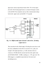
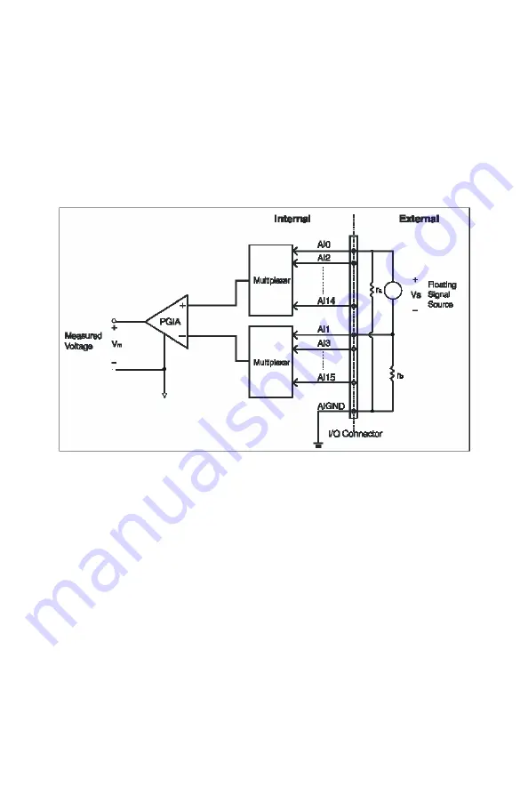
signal source and an input channel on the MIC-3716. In this figure,
each side of the floating signal source is connected through a resistor
to the AIGND. This connection can reject the common-mode voltage
between the signal source and the MIC-3716 ground.
Fig. 3-4: Differential input channel connection - floating
signal source
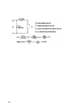
This connection has the disadvantage of loading the source down with
the series combination (sum) of the two resistors. For r
a
and r
b,
for
example, if the input impedance r
s
is 1 k
Ω
, and each of the two
resistors are 100 k
Ω
, then the resistors load down the signal source
with 200 k
Ω
(100 k
Ω
+ 100 k
Ω
), resulting in a –0.5% gain error. The
following gives a simplified representation of the circuit and
calculating process.
Содержание MIC-3716
Страница 2: ...ii This page is left blank for hard printing...
Страница 6: ...vi This page is left blank for hard printing...
Страница 8: ...viii Table E 2 D A binary code table 117...
Страница 11: ...1 Introduction 1 CHAPTER...
Страница 17: ...7 Fig 1 1 Installation Flow Chart...
Страница 21: ...11 Installation and Configuration CHAPTER 2...
Страница 40: ...30 This page is left blank for hard printing...
Страница 41: ...31 Signal Connections CHAPTER 3...
Страница 44: ...34 Fig 3 1 I O connector pin assignments for the MIC 3716...
Страница 50: ...40...
Страница 54: ...44 This page is left blank for hard printing...
Страница 55: ...45 Software Programming Overview CHAPTER 4...
Страница 60: ...50 This page is left blank for hard printing...
Страница 61: ...51 Calibration CHAPTER 5...
Страница 77: ...67 Appendixes...
Страница 81: ...71 Appendix B Block Diagrams...
Страница 82: ...72 This page is left blank for hard printing...
Страница 120: ...110 This page is left blank for hard printing...


