background image

5

Chapter 1  

Figure 1.2: Details of wallmount brackets

Содержание IPC-6806S

Страница 1: ...IPC 6806S Wallmount IPC Chassis for 6 Half sized Cards User Manual...

Страница 2: ...ch Co Ltd assumes no responsibility for its use nor for any infringements of the rights of third parties which may result from its use Acknowledgements IPC 6806 6806W 6806S are all trademarks of Advan...

Страница 3: ...lacement materials service time and freight Please consult your dealer for more details If you think you have a defective product follow these steps 1 Collect all the information about the problem enc...

Страница 4: ...nce to radio communications Operation of this equipment in a residential area is likely to cause harmful interference in which case the user will be required to correct the interference at his own exp...

Страница 5: ...e a damp cloth Do not use liquid or spray detergents for clean ing 4 For plug in equipment the power outlet socket must be located near the equipment and must be easily accessible 5 Keep this equipmen...

Страница 6: ...LLED ENVIRONMENT 16 CAUTION DANGER OF EXPLOSION IF BATTERY IS INCORRECTLY REPLACED REPLACE ONLY WITH THE SAME OR EQUIVALENT TYPE RECOMMENDED BY THE MANUFACTURER DISCARD USED BATTERIES ACCORD ING TO TH...

Страница 7: ...zw elektrischen Schlag ausl sen 13 ffnen Sie niemals das Ger t Das Ger t darf aus Gr nden der elektrischen Sicherheit nur von authorisiertem Servicepersonal ge ffnet werden 14 Wenn folgende Situatione...

Страница 8: ...iche Verantwortung f r die Richtigkeit der in diesem Zusammenhang get tigten Aussagen ab Safety Precaution Static Electricity Follow these simple precautions to protect yourself from harm and the prod...

Страница 9: ...py disk drive 13 2 4 Installing add in cards 13 2 5 Installing wallmount brackets 15 Chapter 3 Operation 18 3 1 The Front Section of IPC 6806S 18 3 1 1 Switches 18 3 1 2 LED indicators 18 3 2 Replacin...

Страница 10: ...IPC 6806S User Manual iv B 2 2 Connectors 28 B 2 3 Connector Pin Definition 28...

Страница 11: ...2 CHAPTER 1 General Information...

Страница 12: ...2 Specifications Construction Heavy duty steel Disk drive capacity One 3 5 FDD and one internal 3 5 HDD Indicators on front panel LEDs for Power On Off and HDD Switches on front panel Power switch and...

Страница 13: ...0 60 Hz Full range Output voltage 5 V 16 A 3 3 V 10 A 12 V 9 A 12 V 0 7 A 5 V 0 2 A 5 Vsb 1 5 A Minimum load 5 V 2 A 12 V 1 A 3 3 V 1 A MTBF 84 000 hours 25 C full load Safety CE UL TUV CB CCC 1 5 Pas...

Страница 14: ...IPC 6806S User Manual 4 1 6 Dimensions of IPC 6806S Figure 1 1 Dimensions of IPC 6806S...

Страница 15: ...5 Chapter1 Figure 1 2 Details of wallmount brackets...

Страница 16: ...IPC 6806S User Manual 6...

Страница 17: ...2 CHAPTER 2 System Setup...

Страница 18: ...he name of each part referred to in this manual Note To shorten the total system installation time we sug gest users install a passive backplane first then CPU and add in card s and finally the drive...

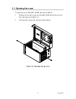
Страница 19: ...To open the cover of the IPC 6806S proceed as follows 1 Remove two screws one on each side which secure the cover to the card cage see Figure 2 1 2 Lift the lid to expose the interior of the chassis...

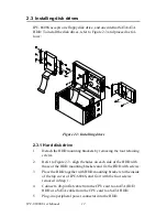
Страница 20: ...ne CPU card IPC 6806S accepts a 6 slot passive backplane to support up to six half sized cards To install a backplane and a CPU card refer to Figure 2 2 and proceed as follows Figure 2 2 Installing a...

Страница 21: ...ly 3 Carefully insert the CPU card in to the master slot of the backplane Make sure that the card bracket has been inserted properly and the other edge of the card has been fixed in the guiding rail F...

Страница 22: ...by removing the four retaining screws 2 Refer to Figure 2 3 align the holes on each side of the HDD with those of the HDD mounting brackets and fix the HDD with screws 3 Place the HDD together with HD...

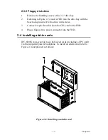
Страница 23: ...Fix the drive with screws 3 Connect 34 pin flat cable from the CPU card to the FDD 4 Plug a floppy drive power connector into the FDD 2 4 Installing add in cards IPC 6806S can accept up to six half si...

Страница 24: ...serted and remove the slot s blank bracket s attached to the rear plate of the chassis 2 Insert a plug in card Make sure that the card bracket has been inserted properly Fasten the card at the top of...

Страница 25: ...To wall mount your chassis refer to Figure 2 5 and proceeds follows Figure 2 5 Install wallmount brackets 1 Attach the wallmount brackets to the bottom of the chassis and fix them with the six provid...

Страница 26: ...IPC 6806S User Manual 16...

Страница 27: ...2 CHAPTER 3 Operation...

Страница 28: ...tem Power On Off Switch Use this switch to turn on off the system power 3 1 2 LED indicators Two LEDs are placed to indicate the system status Please refer to Table 3 1 for the LED summary If the syst...

Страница 29: ...fan filter cover free from the chassis 2 Remove the fan filter and replace it with a new one 3 2 2 Replace the system fan 1 Remove the fan holder from the chassis 2 Unplug the fan power connector 3 R...

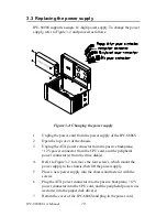
Страница 30: ...from the passive backplane 12V power connector from the CPU card and the peripheral power connector s from the drive disk s 4 Refer to Figure 3 2 to remove the four screws which mount the power suppl...

Страница 31: ...2 APPENDIX A Exploded Diagram...

Страница 32: ...IPC 6806S User Manual 22 Appendix A Exploded Diagram Figure A 1 Exploded Diagram...

Страница 33: ...2 APPENDIX B Passive Backplanes...

Страница 34: ...IPC 6806S User Manual 24 Appendix B Passive Backplanes B 1 PCA 6106 B 6 slot ISA backplane B 1 1 Dimension Drawing Size 140 2 x 175 mm...

Страница 35: ...3 KB Out 5 pin external K B connector AT1 AT power connector ATX1 ATX power connector CN1 PS ON function 3 pin connector to CPU card for ATX sig nal CN2 8 pin alarm board power connector CN3 3 pin 5V...

Страница 36: ...Pin Signal Pin Signal 1 3 3V 6 5V 11 3 3V 16 GND 2 3 3V 7 GND 12 12V 17 GND 3 GND 8 NC 13 GND 18 5V 4 5V 9 5VSB 14 PS ON 19 5V 5 GND 10 12V 15 GND 20 5V Pin Signal 1 PS ON 2 GND 3 5VSB Pin Signal Pin...

Страница 37: ...27 AppendixB B 2 PCA 6105P5 0B1 5 slot PCI backplane B 2 1 Dimension Drawing Size 143 x 176 mm...

Страница 38: ...external K B connector BIG1 Peripheral power connector AT1 AT power connector ATX1 24 pin ATX power connector CN1 PS ON function 3 pin connector to CPU card for ATX signal CN2 8 pin alarm board power...

Страница 39: ...n Signal 1 3 3V 6 5V 11 3 3V 16 GND 2 3 3V 7 GND 12 12V 17 GND 3 GND 8 NC 13 GND 18 5V 4 5V 9 5VSB 14 PS ON 19 5V 5 GND 10 12V 15 GND 20 5V Pin Signal 1 PS ON 2 GND 3 5VSB Pin Signal Pin Signal Pin Si...

Страница 40: ...IPC 6806S User Manual 30 BIG1 Connector Pin Signal 1 12V 2 GND 3 GND 4 5V...

Отзывы: