IPC-6806S User Manual
28
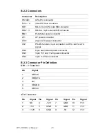
B.2.2 Connectors
B.2.3 Connector Pin Definition
KB1 ~ 3 Connector
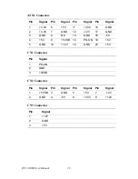
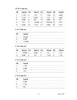
AT1 Connector
Connector
Description
PICMG1
CPU-PCI connector
PCI1 ~ 4
32-bit PCI bus connector
KB1
KB-In, from CPU card K/B connector
KB2 ~ 3
KB-Out, 5-pin external K/B connector
BIG1
Peripheral power connector
AT1
AT power connector
ATX1
24-pin ATX power connector
CN1
PS-ON function, 3-pin connector to CPU card for ATX
signal
CN2
8-pin alarm board power connector
CN3
3-pin +5V and +12V power connector
CN4
3-pin +12V fan connector
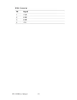
Pin
Signal
1
KBCLK
2
KBDATA
3
NC
4
KBGND
5
KBVCC
Pin
Signal
Pin
Signal
Pin
Signal
Pin
Signal
1
NC
4
-12V
7
GND
10
+5V
2
+5V
5
GND
8
GND
11
+5V
3
+12V
6
GND
9
-5V
12
+5V
Содержание IPC-6806S
Страница 1: ...IPC 6806S Wallmount IPC Chassis for 6 Half sized Cards User Manual...
Страница 10: ...IPC 6806S User Manual iv B 2 2 Connectors 28 B 2 3 Connector Pin Definition 28...
Страница 11: ...2 CHAPTER 1 General Information...
Страница 14: ...IPC 6806S User Manual 4 1 6 Dimensions of IPC 6806S Figure 1 1 Dimensions of IPC 6806S...
Страница 15: ...5 Chapter1 Figure 1 2 Details of wallmount brackets...
Страница 16: ...IPC 6806S User Manual 6...
Страница 17: ...2 CHAPTER 2 System Setup...
Страница 26: ...IPC 6806S User Manual 16...
Страница 27: ...2 CHAPTER 3 Operation...
Страница 31: ...2 APPENDIX A Exploded Diagram...
Страница 32: ...IPC 6806S User Manual 22 Appendix A Exploded Diagram Figure A 1 Exploded Diagram...
Страница 33: ...2 APPENDIX B Passive Backplanes...
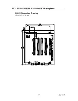
Страница 37: ...27 AppendixB B 2 PCA 6105P5 0B1 5 slot PCI backplane B 2 1 Dimension Drawing Size 143 x 176 mm...
Страница 40: ...IPC 6806S User Manual 30 BIG1 Connector Pin Signal 1 12V 2 GND 3 GND 4 5V...


