29
iDAQ-731_751_763D User Manual
C
ha
pte
r 3
Fu
nc
tio
n D
eta
ils
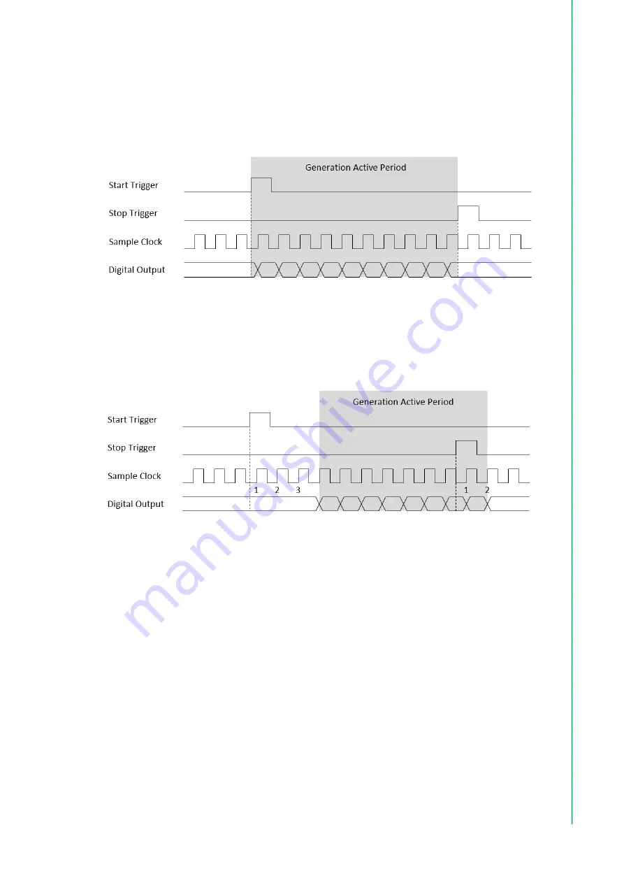
The start and stop of the generation are controlled by the start trigger and stop trig
-
ger, respectively. When configuration is completed, the acquisition engine of the
iDAQ chassis is at standby state. After receiving a start trigger, generation becomes
active and each rising edge of the sample clock converts one analog output sample.
The generation active period lasts until a stop trigger is received, which ends the gen
-
eration. This is shown in Figure 3.21.
Figure 3.21 Start and stop of the digital output waveform generation.
The start and stop of generation can also be delayed in number of samples after
receiving the corresponding trigger signal. As shown in Figure 3.22, the start of gen
-
eration is delayed by 3 samples after receiving a start trigger, and the stop of genera
-
tion is delayed by 2 samples after receiving a stop trigger.
Figure 3.22 Start and stop of the digital output waveform generation with delay.
Refer to section 3.1 Trigger and Timing Signal Output for possible signal routings and
configurations for these timing signals (start trigger, stop trigger, and sample clock).
Buffered digital output waveform generation has several advantages over static digi
-
tal output update:
The start and stop time of generation (or duration of the generation) can be pre
-
cisely controlled by hardware trigger signals.
Update rate can be much higher by using hardware sample clock signal.
Time between samples is deterministic.
3.5.3
Digital Output Fail-Safe Function
When upstream communication is disconnected, the state of the digital output chan
-
nels cannot be controlled by the software anymore and will keep at the last state
before disconnection. This may cause harmful operation for the external devices
which is begin controlled by the digital output channels.
The digital output fail-safe function can be enabled to solve this problem. If enabled,
the state of the digital output channels will be automatically set to the pre-pro
-
grammed fail-safe values when disconnection occurs. After reconnection, the state
can again be controlled by the software.
Содержание iDAQ-731
Страница 1: ...User Manual iDAQ 731 iDAQ 751 iDAQ 763D Digital I O and Relay Industrial DAQ Modules ...
Страница 8: ...iDAQ 731_751_763D User Manual viii ...
Страница 11: ...Chapter 1 1 Start Using IDAQ 731 751 763D ...
Страница 16: ...iDAQ 731_751_763D User Manual 6 ...
Страница 17: ...Chapter 2 2 Installation and Field Application ...
Страница 28: ...iDAQ 731_751_763D User Manual 18 ...
Страница 29: ...Chapter 3 3 Function Details ...
Страница 42: ...iDAQ 731_751_763D User Manual 32 Figure 3 27 Streaming generation with retrigger ...
Страница 44: ...iDAQ 731_751_763D User Manual 34 ...
Страница 45: ...Appendix A A Specifications ...
Страница 49: ...39 iDAQ 731_751_763D User Manual Appendix A Specifications A 7 Function Block iDAQ 731 iDAQ 751 iDAQ 763D ...
Страница 50: ...iDAQ 731_751_763D User Manual 40 ...
Страница 51: ...Appendix B B System Dimensions ...
Страница 52: ...iDAQ 731_751_763D User Manual 42 B 1 iDAQ Modules ...
Страница 53: ...43 iDAQ 731_751_763D User Manual Appendix B System Dimensions ...


