background image

FWA-6500 Startup Manual  5

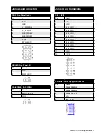
CN12 : Front Panel Header

Pins

Result

1

VCC

2

GND

3

JP_PWRBTN#

4

FP_SYS_RST#

5

SMB_PWRCLK

6

SMB_PWRDAT

7

VCC3

8

SATA_LED_C

HD_LED : Front Panel LED

Pins

Result

1

VCC

2

SATA_LED_C

CASE_OPEN : CASE OPEN

Pins

Result

1

BMC_CASEOP#

2

GND

  Jumpers and Connectors

CN13 : GPIO

Pins

Result

1

VCC

2

GND

3

9554_GPIO_0

4

9554_GPIO_1

5

9554_GPIO_2

6

9554_GPIO_3

7

9554_GPIO_4

8

9554_GPIO_5

9

9554_GPIO_6

10

9554_GPIO_7

11

GND

12

VCC3

CN-IPMB0 : Power Supply ACPI function

Pins

Result

1

IPMB0_SMBCLK

2

IPMB0_SMBDAT

3

IPMB0_ALERT#

4

GND

5

BMC_3VSB

  Jumpers and Connectors

Содержание FWA-6500

Страница 1: ...Bus 4 x Gen 2 PCIe x8 connected to express module 1 x Gen 1 PCIe x4 connected to management board 1 x Gen 1 PCIe x4 slot for riser card 1 x Gen 2 PCIe x4 slot for riser card CF Interface JMicron SATA to IDE bridge 1 x CF socket Storage 2 x 2 5 removable SATA HDD docks 2 x 3 5 removable SATA HDD docks for option Remote Management Supportc Hitachi H8 BMC com pliant with IPMI 2 0 Peripherals USB 2 x ...

Страница 2: ...sion only Dimensions W x D 72 x 172 mm Figure 1A NAEM 0101 4 ports RJ45 Module Figure 2A NAEM 0102 4 ports SFP Module Figure 3A NAEM 1001 2 ports SFP Module Installing the CPUs 1 Locate the CPU sockets on the board 2 Taking one CPU at a time remove the protective shield if present and press the load lever and move it until it is clear of the retention tab and raise it 3 Make sure that the alignmen...

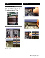
Страница 3: ...small dab of heat transfer compound to the top of the installed CPU and then align it and carefully lower the heat sink into place 2 Insert and loosely engage each heat sink screw Then screw them in carefully to secure the heat sink Installing the Riser Cards 1 There are two screws on the base chassis 2 Please release the screw and remove the bracket 3 Remove the bracket Installation Installation ...

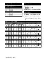
Страница 4: ...50 PIN CN12 Front Panel Header CN13 GPIO Connector CN15 PS2 Header CN16 USB Pin Header CN18 COM Header HD_LED Front Panel LED CASE_OPEN Case Open SW PCIE IOH PCIe Switch From IOH CN IPMB0 Power Supply ACPI function Jumpers and Connectors Jumpers and Connectors LR_COMS CMOS clear function Pins Result 1 2 Keep CMOS data 2 3 Clear CMOS data Default Keep CMOS data Clear CMOS data SW BMC Update and Res...

Страница 5: ...CC 2 SATA_LED_C CASE_OPEN CASE OPEN Pins Result 1 BMC_CASEOP 2 GND Jumpers and Connectors CN13 GPIO Pins Result 1 VCC 2 GND 3 9554_GPIO_0 4 9554_GPIO_1 5 9554_GPIO_2 6 9554_GPIO_3 7 9554_GPIO_4 8 9554_GPIO_5 9 9554_GPIO_6 10 9554_GPIO_7 11 GND 12 VCC3 CN IPMB0 Power Supply ACPI function Pins Result 1 IPMB0_SMBCLK 2 IPMB0_SMBDAT 3 IPMB0_ALERT 4 GND 5 BMC_3VSB Jumpers and Connectors ...

Страница 6: ...CIe Switch from IOH SW PCIe IOH PEWIDTH 5 0 PCIe A PCIe B PCIe C PCIe D SW 1 12 SW 2 11 SW 3 10 SW 4 9 SW 5 8 SW 6 7 ON ON ON ON ON ON x4 x4 x4 x4 x4 x4 x4 x4 ON ON OFF OFF OFF OFF x8 x8 x8 x8 OFF OFF OFF OFF OFF OFF Wait on BIOS ON ON ON ON ON OFF x4 x4 x4 x4 x8 x4 x4 ON ON ON ON OFF ON x4 x4 x4 x4 x4 x4 x8 ON ON ON ON OFF OFF x4 x4 x4 x4 x8 x8 ON ON ON OFF ON ON x8 x4 x4 x4 x4 x4 x4 ON ON ON OFF...

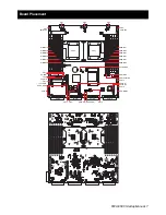
Страница 7: ...C CLR CMOS SW PCIE IOH PCIE G2 PCIE G1 DIMMC1 DIMMC2 DIMMB1 DIMMB2 DIMMA1 DIMMA2 DIMMF1 DIMMF2 DIMME1 DIMME2 DIMMD1 DIMMD2 CN12 HD_LED LPT1 FP_PWR CN11 12 x 2 PWR SATA4 SATA3 SATA1 SATA2 CASE_OPEN PCIE E PCIE A PCIE B PCIE C PCIE D CN1 CN4 PWR 2X4 CN5 PWR 2X4 CPU0 CPU1 CN3 CN2 4 9 6 4 1 1 6 3 2 1 7 3 3 4 8 ...

Страница 8: ...oltage and current rating marked on the product All cautions and warnings on the equipment should be noted If the equipment is not used for long time disconnect it from the power source to avoid being damaged by transient over voltage Never pour any liquid into ventilation openings This could cause fire or electrical shock Never open the equipment For safety reasons the equipment should be opened ...

Страница 9: ... Rack Mount Instructions The following or similar rack mount instructions are included with the installation instructions A Elevated Operating Ambient If installed in a closed or multi unit rack assembly the operating ambient temperature of the rack environment may be greater than room ambient Therefore consideration should be given to installing the equipment in an environment compatible with the...

Отзывы: