4 FWA-6500 Startup Manual
Installation
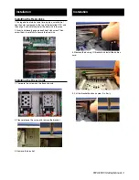
Installing the Memory
The FWA-6500 system provides 12 x DDR3 DIMMs which
can support up to DDR3 1333MHz 96GB.
1. To install the memory, please start to install the memory
from CPU0 with DIMMA1.
The board has a number of jumpers that allow you to con-
figure your system to suit your application. The table below
lists the function of each of the jumpers and connectors.
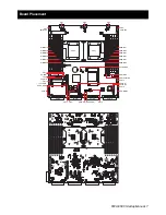
Connector / Jumper List
LR_CMOS
Clear COMS
SW-BMC
Update and Reset BMC firmware
CN1
System FAN
CN2
System FAN
CN3
System FAN
CN10
Compact Flash socket 50 PIN
CN12
Front Panel Header
CN13
GPIO Connector
CN15
PS2 Header
CN16
USB Pin Header
CN18
COM Header
HD_LED
Front Panel LED
CASE_OPEN
Case Open
SW-PCIE-IOH
PCIe Switch (From IOH)
CN-IPMB0
Power Supply ACPI function
Jumpers and Connectors
Jumpers and Connectors
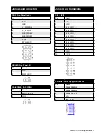
LR_COMS: CMOS clear function
Pins
Result
1-2
Keep CMOS data*
2-3
Clear CMOS data
*: Default
Keep CMOS data* Clear CMOS data
SW-BMC: Update and Reset BMC firmware
Pins
Result
1-4
Update BMC
2-3
Reset BMC
*: Default
Default* Update BMC Reset BMC
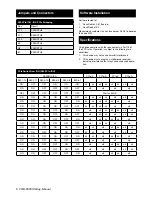
JP-WDT: Watchdog Header
Pins
Result
1-2
Ignore WDT for LAN bypass enable
2-3
Normal WDT function*
*: Default
Ignore WDT for LAN Bypass Normal WDT function*
JP-WDT: System Reset Header
Pins
Result
1-2
Ignore WDT for LAN bypass enable
2-3
Normal WDT function*
*: Default


