background image


Package Contents 

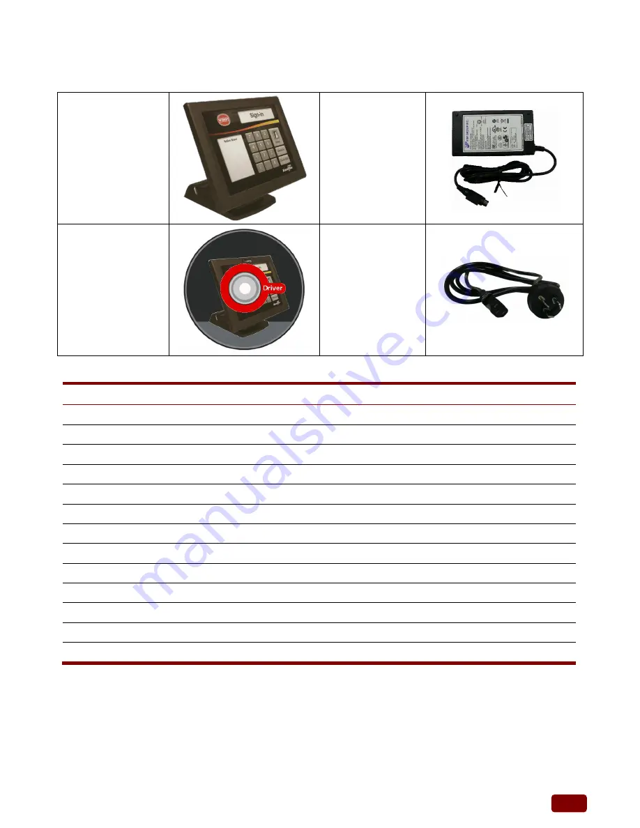
The following items come standard with the EP-55XX series: 
 

POS System 


Power Adaptor 


Utility and Main 

Board Chipset 

Driver CD 


AC Power Cord 


Options 


Magnetic Stripe Reader (MSR) Module: triple track 


2-in-1 Module (Magnetic Stripe  Fingerprint Reader) 


2-in-1 Module (Magnetic Stripe  I-Button Reader) 


2-in-1 Module (Magnetic Stripe  IC Card Reader) 


2-in-1 Module (Magnetic Stripe  RFID 13.56MHz ISO 14443A Mifare) 


2-in-1 Module (Magnetic Stripe  WiFi 802.11b/g/n or Bluetooth 2.0) 


2-in-1 Module (Magnetic Stripe  Bluetooth) 


3-in-1 Module (Magnetic Stripe  I-Button  IC Card Reader) 


3-in-1 Module (Magnetic Stripe  I-Button  RFID 13.56MHz ISO 14443A Mifare ) 


VFD Customer Display: 9 mm height, 2 lines 20 characters each 


2nd Customer Display: 8.9” or 15”, tempered glass LCD 15 cm set on a 15 cm tube pole 


VESA Mount Bracket for Wall Mount 


Swing-arm Mounts, adjustable angle VESA for Pole Mount 


Содержание EP-55XX-AR10

Страница 1: ...EP 55XX Series Efficiency All in One Point of Sales System User Manual Ver 3 0_2014 02 14 Before installing and operating the unit please read this user manual thoroughly and retain for reference...

Страница 2: ...ID WiFi Bluetooth pole type 2nd display and cash drawer Chapter 4 PEB 973A PEB 973D INS8313B and GA D525E C6 main board diagrams locations of jumpers and connectors Also shows the external COM6 port p...

Страница 3: ...ncouraged to try to correct the interference by one or more of the following measures Reorient or relocate the receiving antenna Increase the separation between the equipment and the receiver Connect...

Страница 4: ...tains information protected by copyright No part of this manual may be photocopied or reproduced in any form without prior written consent from the manufacturer The software described in this guide is...

Страница 5: ...nd for the voltage and current marked on the product s electrical ratings label The voltage and current rating of the cord should be greater than the voltage and current rating marked on the product 1...

Страница 6: ...17 Removing and Replacing the SATA Hard Disk 20 Chapter 3 Optional Components and Peripherals 23 Module Installation 23 Single MSR Module Installation 25 Cash Drawer Installation 27 Pole Type 2nd Disp...

Страница 7: ...for Windows 7 53 Wireless LAN Driver Installation optional 54 MSR Driver Installation optional 57 Fingerprint Reader Driver Installation optional 58 IC Card Reader Driver Installation optional 60 Rear...

Страница 8: ...B SO DIMM DDR2 SDRAM 800MHz EP 55XX AR30 40 Supports a max 1 x 4GB SO DIMM DDR3 SDRAM 1333MHz Video Memory Supports Intel DVMT shared system memory Compact Flash Supports 1 x Compact Flash Card Type I...

Страница 9: ...100 1000Mbps Base T RJ45 connector for EP5530 XX40 Audio Port 1 x Line out 1 x Mic in Speaker 2 x internal stereo 2W speakers Mechanics and Environment Construction Plastic housing Dimensions 272 D x...

Страница 10: ...r 2 in 1 Module Magnetic Stripe Reader RFID 13 56MHz ISO 14443A Mifare 2 in 1 Module Magnetic Stripe Reader WiFi 802 11b g n or Bluetooth 2 0 2 in 1 Module Magnetic Stripe Reader Bluetooth 3 in 1 Modu...

Страница 11: ...4 Base System Before you begin take a few moments to become familiar with the EP 55XX series The rear of the system Right Speaker Left Speaker Touch Screen Base...

Страница 12: ...erface MSR IC Card Reader MSR for PS 2 interface IC Card Reader for USB interface MSR RFID MSR for PS 2 interface 13 56 MHz 14443A Mifare RFID for USB interface MSR WiFi MSR for PS 2 interface Wifi fo...

Страница 13: ...ng messages and announcements Three types of pole mount display choices are available a 8 9 LCD monitor 15 LCD monitor and a 9 cm high 2 lines with 20 characters each VFD The pole mount is located at...

Страница 14: ...7 EP 55XX Series with 8 9 2nd Display Dimensions Unit mm...

Страница 15: ...port and can not transmit the full range of RS 232C signals Refer to Chapter 4 for COM6 pin assignments For PEB 973A D main board For INS8313B main board LAN 12VDC In VGA 12V Cash Drawer COM1 2 5 RI...

Страница 16: ...9 For GA D525E C6 main board USBX2 COM6 for pole Display Cash Drawer Line Out VGA USBX2 12VDC In LAN LPT1 COM1 COM2 COM5 LAN...

Страница 17: ...face controller receptacles Do not disable the power cord grounding plug The grounding plug is an important safety feature Plug the power cord in a grounded earthed outlet that is easily accessible at...

Страница 18: ...ternal devices CAUTION Regardless of the power on state voltage is always present on the main board as long as the system is plugged into an active AC outlet You must disconnect the power cord to avoi...

Страница 19: ...atic electricity While handling a drive avoid touching the connector 1 Turn off the system power properly through the operating system then turn off any external devices 2 Disconnect the power cord fr...

Страница 20: ...13 5 Unscrew the eight screws as shown below to remove it 6 Open the metal cover in the direction of the arrow...

Страница 21: ...m is plugged into an active AC outlet The power cord must be disconnected from the power source before clearing the CMOS NOTE All LEDs on the board should be OFF Failure to ensure there is no power in...

Страница 22: ...cord to avoid damage to the internal components of the system 3 Remove the panel back cover and metal cover CAUTION To avoid scratching the panel while dismantling the system first place a piece of c...

Страница 23: ...of both the CF card and hard disk at the same time however the user will need to set the system BIOS for the preferred boot order When either a CF card only or 2 5 hard disk only is installed the BIOS...

Страница 24: ...tronic components of the system or optional cards Before beginning these procedures ensure that you are discharged of static electricity by briefly touching a grounded metal object When handling a mem...

Страница 25: ...eplaced pull the ends of both metal latches away from the card to release it NOTE A memory card can be installed in only one way Match the notch on the card with the tab in the memory socket 6 Insert...

Страница 26: ...ory Ensure the thermal pad and the top surface of the memory is in total contact to prevent the memory from overheating Overheating may result in unstable system performance 8 Reconnect the power cord...

Страница 27: ...tions that were preinstalled on the system 1 Turn off the system power properly through the operating system then turn off any external devices 2 Disconnect the power cord from the power outlet and di...

Страница 28: ...he sides of the HDD box remove all four screws and lift out the hard disk 8 Insert the replacement hard disk into the HDD box and re secure the screws 9 Slide the HDD box back into the case and screw...

Страница 29: ...rosoft earlier OS such as XP POS Ready2009 You should install support tools offered by original supplier to align the performence of HDD Otherwise HDD life will be reduced about 48 You can get the ali...

Страница 30: ...ny external devices CAUTION Regardless of the power on state voltage is always present on the main board as long as the system is plugged into an active AC outlet You must disconnect the power cord to...

Страница 31: ...cord and any external devices then turn on the system NOTE The MSR module configuration tool is in the included CD If you need configure MSR module please execute the utility according to the procedur...

Страница 32: ...s of the power on state voltage is always present on the main board as long as the system is plugged into an active AC outlet You must disconnect the power cord to avoid damage to the internal compone...

Страница 33: ...cord and any external devices then turn on the system NOTE The MSR module configuration tool is in the included CD If you need configure MSR module please execute the utility according to the procedur...

Страница 34: ...stalled 1 Turn off the system power properly through the operating system then turn off any external devices 2 Disconnect the power cord from the power outlet and disconnect any external devices CAUTI...

Страница 35: ...nect any external devices CAUTION Regardless of the power on state voltage is always present on the main board as long as the system is plugged into an active AC outlet You must disconnect the power c...

Страница 36: ...respectively 6 Reconnect the power cord and any external devices then turn on VFD LCD power Finally turn on the system power NOTE The pole mount VFD module s configuration utility is in the included C...

Страница 37: ...into an active AC outlet You must disconnect the power cord to avoid damage to the internal components of the system 3 Connect the VFD module s cable connector to the socket on the top of panel back c...

Страница 38: ...ations Connector Function J1 LPC port 80 daughter card connector J2 SATA and IDE active LED J3 SATA drive power connector J4 Reserved J5 LVDS back light inverter connector J6 USB port 2 J7 SATA port 0...

Страница 39: ...rt J16 USB port 1 USB port 4 and GIGA LAN RJ 45 connector J17 Speaker out and MIC connector J18 COM1 COM2 connector Upper is COM1 Lower is COM2 J19 RJ 11 connector J21 12V DC power input J22 COM5 conn...

Страница 40: ...a star symbol Clear CMOS Selection PIN No Function 1 2 Short Charge 2 3 Short Clear CMOS CF Card Master Slave Selection PIN No Function 1 2 Short Master 1 2 Open Slave LVDS Panel VDD Selection PIN No...

Страница 41: ...COM1 RI Function Selection PIN No Function 1 2 3 4 5 6 Short 5V output Short RI function Short 12V output COM2 RI Function Selection PIN No Function 1 2 3 4 5 6 Short 5V output Short RI function Shor...

Страница 42: ...35 Jumper and Connector Locations of PEB 973D For EP 55XX AR20...

Страница 43: ...nector J13 CPU FAN J14 SYS FAN J15 Print Port Connector J16 POWER DC 12V Connector J17 POWER DC 12V Connector J18 Front panel pin header J19 HDD LED Pin header J20 AUDIO JACK Connector J21 CASH DRAWER...

Страница 44: ...e 2 3 Short Clear CMOS CF Card Master Slave Selection PIN No Function 1 2 Short Master 1 2 Open Slave LVDS Panel VDD Selection PIN No Function 1 2 Short 3 3V 2 3 Short 5V LVDS Back Light Enable Level...

Страница 45: ...utput Short RI function Short 12V output COM2 RI Function Selection PIN No Function 1 2 3 4 5 6 Short 5V output Short RI function Short 12V output COM5 RI Function Selection PIN No Function 1 2 3 4 5...

Страница 46: ...39 Jumper and Connector Locations of INS8313B and GA D525E C6 For EP 55XX AR30 40...

Страница 47: ...connector F_AUDIO Front_Audio connector F_USB 1 USB connector F_USB 2 USB connector F_USB 3 USB connector SATA 1 7 pin SATA connector SATA 2 7 pin SATA connector SATA 3 7 15 pin SATA connector SATAPW...

Страница 48: ...LVDS 3V 5V selection PIN No Function 1 2 Short 3 3V 2 3 Short 5V Jumper for RS232 RS422 and RS485 connectors PIN No Function 1 2 Short RS232 3 4 Short RS422 5 6 Short RS485 COM2 Pin 1 PIN No Function...

Страница 49: ...5V or VCC 5V selections PIN No Function 1 2 Short VCC 5V 2 3 Short Stand by 5V Clear CMOS Pin header PIN No Function 1 2 Short Clear CMOS 2 3 Short Charge External COM6 Por Connector Pin Definitions P...

Страница 50: ...43 LCD Power ON OFF PIN No Function 1 2 Short ON 1 2 Open OFF Back light Inverter Enabled Disabled PIN No Function 1 2 Short Enable 1 2 Open Disable BKLTEN_CON LCDPWR_CON...

Страница 51: ...perating systems A software CD is included in the package contents The following section documents the procedures used to install the peripheral 1 Insert sofeware CD into a system 2 Run the setup exe...

Страница 52: ...t your POS model Number 6 Select the driver that you want to install and then follow on screen instructions to install your driver or refer to following procedures specifying how every driver is to be...

Страница 53: ...tel Chipset Driver Installation 1 Click the Next button on the Welcome screen 2 Click Yes on the License Agreement screen 3 Click Next on the Information screen 4 When installation is complete click F...

Страница 54: ...on the Starup screen 2 Click Next on the Welcome screen 3 Click Yes on the License Agreement screen 4 Click Next on the Information screen 5 Click Next on the Setup Progress screen 6 When installatio...

Страница 55: ...Welcome screen 2 Click Unzip on the WinZip Self Extractor screen 3 Select Default installation language click Next 4 Select Install Serial Touchscreen Drivers click Next 5 Click Yes on the License Agr...

Страница 56: ...49 7 Select COM3 click Next 8 Click Next to confirm COM port selection 9 Click Finish 10 Click Restart Now to apply these change...

Страница 57: ...on the Welcome screen 2 Click Next to confirm destination location 3 Select Install RS232 driver and click Next 4 Click Install to begin installation 5 Click Finish to complete 6 For Windows 7 operat...

Страница 58: ...51 7 For Windows XP operating system click Continue anyway 8 Click OK to reboot the system 9 Run the Touch Tool on the desktop 10 Select Advance and click on the 4 Pts Calibration button...

Страница 59: ...52 Audio Driver Installation 1 Click Next on the Welcome screen 2 When installation is complete click Finish to restart the system...

Страница 60: ...53 Ethernet Driver Installation for Windows XP 1 Click Next 2 Click Install 3 Click Finish Ethernet Driver Installation for Windows 7 1 Click Install 2 Click Finish...

Страница 61: ...802 11bgn folder and then run the IS_AP_STA_RT2870_D exe 2 Click Accept on the License Agreement screen 3 Alternative and then click Next 4 For Windows XP operating system select Configuration Tool 5...

Страница 62: ...55 8 When installation is complete the WLAN utility will automatically appear on the desktop...

Страница 63: ...lug in the RFID Module 2 Enter the MF320U folder and then run the MifareDemoSetup_PSW00020 exe 3 Click Next 4 Click Next to accept the Destination Directory 5 Click Next after making sure the folder 6...

Страница 64: ...R module 2 Select your MSR interface PS2 or USB 3 For PS2 interface Run the MSRfgSetup_V1_4R7_PSW00025 exe For USB interface Enter the Software folder and then run the HISD_MSR_PSW00003 exe 4 Follow o...

Страница 65: ...ule 2 Enter the SDK folder and then run the setup exe 3 Click Next on the Welcome screen 4 Click Next on the License Agreement screen 5 Click Next to accept the destination folder 6 Click Next to begi...

Страница 66: ...59 9 Wait as the driver is installed 10 Click Finish 11 Click Yes to restart the system required...

Страница 67: ...ader module 2 Enter the EZ100PU Driver folder 3 Select your POS operating system and then run the setup exe 4 Select language click OK 5 Click Next on the Welcome screen 6 Click Install to begin the i...

Страница 68: ...a Serial interface so in order to enable it you must install the included USB to Serial interface driver 1 First plug in the VFD Module 2 Enter the USB To COM Driver folder and then run utility progra...

Страница 69: ...ation required for Cash Drawer 1 Click Next on the Welcome screen 2 Click Install on the Ready to Install screen 3 Click Finish on the Completing installation screen A system restart is required to co...

Страница 70: ...Drawer MSR I Button KeyLock RFID VFD Line Display 1 Click Next on the Welcome screen 2 Click Next on the ReadMe screen 3 Click Next to confirm the Destination Location 4 Click Yes to backup the CCO fi...

Страница 71: ...64 7 Click Finish on the Installation Complete screen...

Страница 72: ...65 OPOS Driver Installation 1 Click Next on the Welcome screen 2 Click Install on the Setup screen 3 Click Finish on the Completing installation screen...

Страница 73: ...SHARE_READ FILE_SHARE_WRITE NULL OPEN_EXISTING FILE_ATTRIBUTE_NORMAL 0 if m_hFile INVALID_HANDLE_VALUE AfxMessageBox Unable to open Cash Drawer Device Driver return Turn on the Cash Drawer Output Fire...

Страница 74: ...TL_CODE NULL 0 ReadByte sizeof ReadByte ulBytesReturned NULL if bRet FALSE ulBytesReturned 1 AfxMessageBox Failed to Read from cash drawer driver CloseHandle hFile return else AfxMessageBox ReadByte D...

Страница 75: ...nst OPEN_EXISTING As Long H3 FILE_ATTRIBUTE_NORMAL As Long H80 Const INVALID_HANDLE_VALUE As Long HFFFFFFFF Const ADVPORT_TYPE As Long 40000 METHOD_BUFFERED As Long 0 FILE_ANY_ACCESS As Long 0 Dim ADV...

Страница 76: ...Handles Timer1 Tick Dim iBytesRtn As Integer Dim iRet As Integer iStatus As Integer Get Drawer Status iRet DeviceIoControl DeviceHandle ADV_STATUS_CTL_CODE 0 0 iStatus 4 iBytesRtn 0 If iRet 0 Or iByt...

Страница 77: ...ong As Long CreateFile Custom Variables Private Type SECURITY_ATTRIBUTES nLength As Long lpSecurityDescriptor As Long bInheritHandle As Long End Type DeviceIoControl Custom Variables Private Type OVER...

Страница 78: ...ADV_OPEN_CTL_CODE iDrawer 4 0 0 iBytesRtn SA1 If iRet 0 Or iBytesRtn 1 Then MsgBox Error opening ADVSYS sys Error Err LastDllError End If End Sub Private Sub Command2_Click Dim iBytesRtn As Long Dim i...

Отзывы: