EKI-1526(TI) | 1528(TI) User Manual
14
2.2.3
Power Connection
The following is only available for EKI-1528/EKI-1528I/EKI-1526/EKI-1526I.
Connect the EKI-1528/EKI-1528I or EKI-1526/1526I AC power line with its AC con-
nector. If the power is properly supplied, you can turn on the power switch and the
PWR LED will light green.
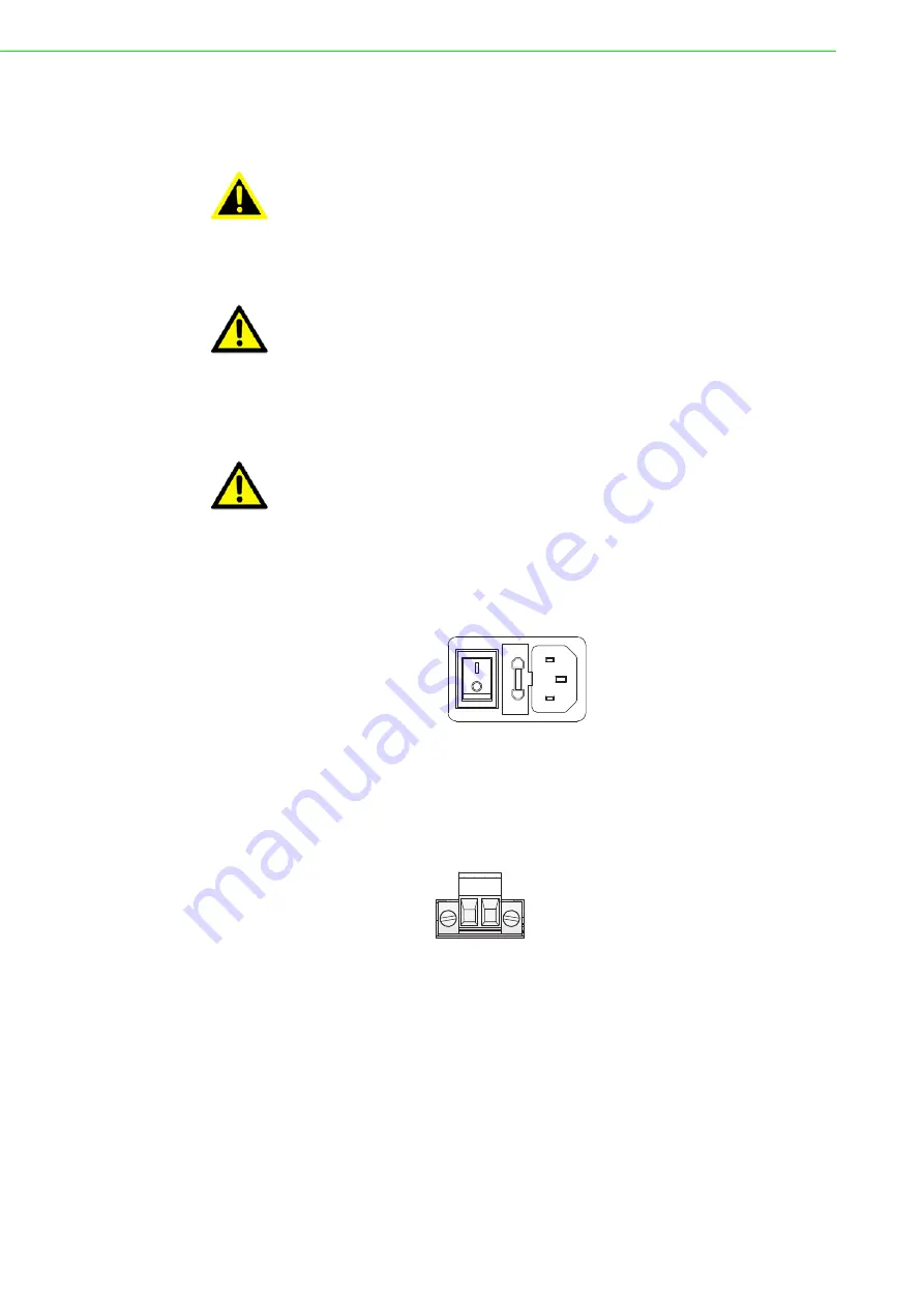
Figure 2.16 Connecting AC Power
The following is only available for EKI-1528T/EKI-1528TI/EKI-1526T/EKI-1526TI.
Connect the DC power connector on the rear panel of the switch to the external
power source with the included power cord, and check the power LED is on. The fol-
lowing figure illustrates the power socket location on the rear side of a EKI-1528T/
EKI-1528TI or EKI-1526T/EKI-1526TI switch.
Figure 2.17 Connecting DC Power
Warning!
Power down and disconnect the power cord before servicing or wiring
the serial device server.
Caution!
Do not disconnect modules or cabling unless the power is first switched
off.
The device only supports the voltage outlined in the type plate. Do not
use any other power components except those specifically designated
for the serial device server.
Caution!
Disconnect the power cord before installation or cable wiring.
USE ONLY WITH A 250V FUSE
V- V+
DC 12~48V
Содержание EKI-1526
Страница 1: ...User Manual EKI 1526 I TI EKI 1528 I TI 8 16 port RS 232 422 485 Serial Device Server Rackmount...
Страница 13: ...Chapter 1 1Overview...
Страница 17: ...Chapter 2 2Getting Started...
Страница 27: ...Chapter 3 3Utility Configuration...
Страница 46: ...Chapter 4 4Selecting An Operating Mode...
Страница 54: ...Chapter 5 5Setting Up Virtual COM Redirector...
Страница 63: ...Chapter 6 6Web Configuration...
Страница 84: ...Chapter 7 7Telnet...
Страница 94: ...Chapter 8 8TCP and UDP Port Numbers...


