


EKI-1511L User Manual
9
2.3
Connecting Hardware
2.3.1
DIN Rail Mounting
The DIN rail mount option is the quickest installation option. Additionally, it optimizes
the use of rail space.
The metal DIN rail kit is secured to the rear of the switch. The device can be mounted
onto a standard 35 mm (1.37”) x 7.5 mm (0.3”) height DIN rail. The devices can be
mounted vertically or horizontally. Refer to the following guidelines for further infor-
mation.
2.3.1.1
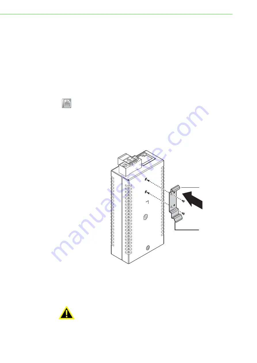
Installing the DIN-Rail Mounting Kit
1.
Align the provided DIN bracket with the device. The bracket can be installed on
the left or rear side of the device to accommodate various environments. For
this demonstration, the bracket is depicted on the rear of the device.
2.
Insert the provided screws and tighten them to secure the bracket to the device.
Figure 2.8 Installing the DIN Bracket
3.
Position the rear panel of the switch directly in front of the DIN rail, making sure
that the top of the DIN rail clip hooks over the top of the DIN rail, as shown in the
following illustration.
Make sure the DIN rail is inserted behind the spring mechanism.
Note!
A corrosion-free mounting rail is advisable.
When installing, make sure to allow for enough space to properly install
the cabling.
Warning!
Do not install the DIN rail under or in front of the spring mechanism on
the DIN rail clip to prevent damage to the DIN rail clip or the DIN rail.
DIN rail clip
DIN rail clip
release tab
Содержание EKI-1511L
Страница 1: ...User Manual EKI 1511L 1 Port RS 232 Serial Device Server...
Страница 12: ...Chapter 1 1Introduction...
Страница 14: ...Chapter 2 2Getting Started...
Страница 26: ...Chapter 3 3Utility Configuration...
Страница 42: ...Chapter 4 4Selecting An Operating Mode...
Страница 50: ...Chapter 5 5Setting up Virtual COM Port...
Страница 59: ...Chapter 6 6Web Interface...
Страница 77: ...Chapter 7 7Telnet Serial Console Configuration...
Страница 85: ...Chapter 8 8TCP and UDP Port Numbers...


