background image


22

1.8  Jumper Settings


This section provides instructions on how to configure your motherboard 
by setting the jumpers. It also includes the motherboards's default settings 
and your options for each jumper. 


1.8.1 How to set jumpers


You can configure your motherboard to match the needs of your applica- 
tion by setting the jumpers. A jumper is a metal bridge that closes an elec- 
trical circuit. It consists of two metal pins and a small metal clip (often 
protected by a plastic cover) that slides over the pins to connect them. To 
“close” (or turn ON) a jumper, you connect the pins with the clip. To 
“open” (or turn OFF) a jumper, you remove the clip. Sometimes a jumper 
consists of a set of three pins, labeled 1, 2, and 3. In this case you connect 
either pins 1 and 2, or 2 and 3. A pair of needle-nose pliers may be useful 
when setting jumpers. 


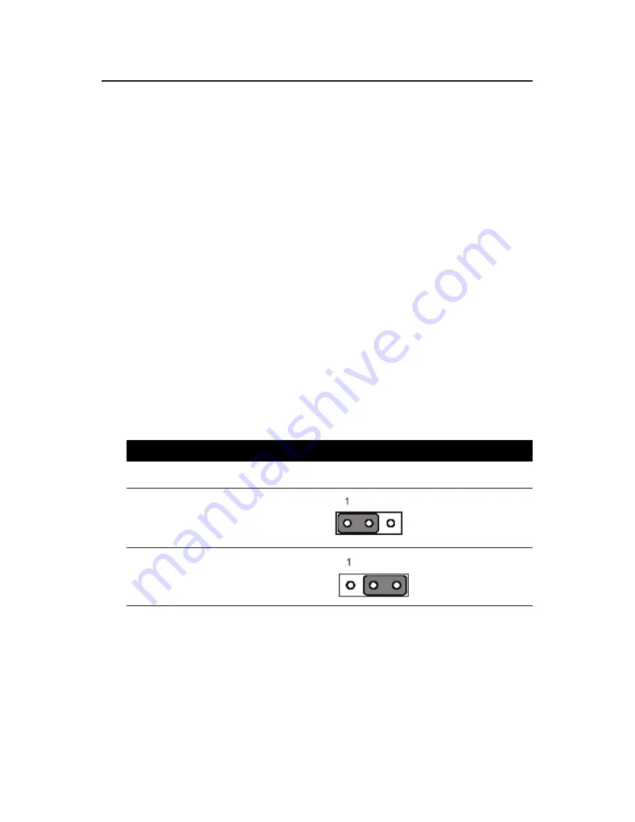
1.8.2 CMOS clear (J3)


The DVMB-554E motherboard contains a jumper that can erase CMOS 
data and reset the system BIOS information. Normally this jumper should 
be set with pins 1-2 closed. If you want to reset the CMOS data, set J1 to 
2-3 closed for just a few seconds, and then move the jumper back to 1-2 
closed. This procedure will reset the CMOS to its default setting. 


Table 1.3: CMOS (J3)


Function


Jumper Setting


* Keep CMOS data 


1-2 closed 


Clear CMOS


data 


2-3 closed 


* default setting 


Содержание DVMB-554E

Страница 1: ...1 DVMB 554E Socket 479 Intel Core 2 Duo Core Duo Core Solo Processor based 533 667 MHz FSB Mini ITX Motherboard with PCI E DDR2 Dual GbE LAN Video Capture User Manual...

Страница 2: ...provided in this manual is intended to be accurate and reliable However Advantech Co Ltd assumes no responsibility for its use nor for any infringements upon the rights of third parties which may res...

Страница 3: ...rmance from your products So if you run into technical difficulties we are here to help For the most fre quently asked questions you can easily find answers in your product doc umentation These answer...

Страница 4: ...rgy and if not installed and used in accordance with the instruction manual may cause harmful interference to radio communications Operation of this device in a residential area is likely to cause har...

Страница 5: ...re details If you think you have a defective product follow these steps 1 Collect all the information about the problem encountered For example type of PC CPU speed Advantech products used other hardw...

Страница 6: ...P N 1700003411 1 CPU Heat Sink P N 1960004032 1 PS 2 Y cable for KB MS P N 1700060202 2 warranty card P N 2190000902 If any of these items are missing or damaged contact your distributor or sales rep...

Страница 7: ...Jumper Settings 22 1 8 1 How to set jumpers 22 1 8 2 CMOS clear J3 22 1 8 3 Watchdog timer output J4 23 1 8 4 COM2 RS 232 422 485 mode selector J2 24 1 8 5 LVDS Power 3 3V 5V selector J6 24 1 9 System...

Страница 8: ...power connector ATX1 36 2 15 GPIO connector GPIO1 37 2 16 LVDS connector VCN1 38 2 17 LCD Inverter Power connector BKL1 39 Chapter 3 Award BIOS Setup 41 3 1 Introduction 41 3 1 1 CMOS RAM Auto backup...

Страница 9: ...5 8 Video BIOS Cacheable 49 3 5 9 Memory Hole At 15M 16M 49 3 5 10 PCI Express Root Port Func 49 3 5 11 PEG Onchip VGA Control 50 3 5 12 On Chip Frame Buffer Size 50 3 5 13 DVMT Mode 50 3 5 14 DVMT F...

Страница 10: ...ower Management 57 3 7 4 Video Off Method 57 3 7 5 Video Off In Suspend 57 3 7 6 Suspend Type 58 3 7 7 Modem Use IRQ 58 3 7 8 Suspend Mode 58 3 7 9 HDD Power Down 58 3 7 10 Soft Off by PWR BTTN 58 3 7...

Страница 11: ...pter 4 Chipset Installation 65 4 1 Before you begin 65 4 2 Introduction 65 4 3 Windows XP Driver Setup 66 Chapter 5 VGA Setup 70 5 1 Introduction 70 5 2 Windows XP Driver Setup 70 Chapter 6 Video capt...

Страница 12: ...12 1 General Information...

Страница 13: ...DVMB 554E also provides incredible visual quality versatile display options 8 bit Dual Channel LVDS and a TV out NTSC PAL interface In addition to powerful computing capabilities the DVMB 554E comes...

Страница 14: ...urring BIOS will check the data and automatically restore the original data for booting Automatically power on after power failure It is often required to have an unattended system come back to operat...

Страница 15: ...one on board pin header RS 232 422 485 Ports can be individually con figured to COM1 COM2 or disabled Keyboard and PS 2 mouse connector One 6 pin Mini DIN connec tors are located on the mounting brac...

Страница 16: ...Q11 The watch dog timer is programmable with each unit equal to one second or one minute 255 levels 1 3 7 Mechanical and environmental specifications Operating temperature 0 60 C 32 140 F Depending on...

Страница 17: ...instructions for connecting external devices to your motherboard Table 1 1 Jumpers Label Function J2 COM2 RS232 422 485 selectors J3 CMOS Clear J4 Watchdog timer output selection J5 AT ATX mode selec...

Страница 18: ...VDO1 DVA 210 connector FN1 FAN connector FN2 FAN connector FN3 FAN connector SMBUS1 SMBus Extend connector SA1 Serial ATA1 SA2 Serial ATA2 VCN1 LVDS connector BKL1 LCD Inverter Power Back light conne...

Страница 19: ...19 1 5 Board Layout Jumper and Connector Locations Figure 1 1 Jumper and Connector locations F i g u r F Figure 1 2 Rear Panel Placement...

Страница 20: ...20 1 6 DVMB 554E Block Diagram Figure 1 3 DVMB 554E Block Diagram...

Страница 21: ...p at all times Place all electronic components on a static dissipative surface or in a static shielded bag when they are not in the chassis Caution The computer is provided with a battery pow ered Rea...

Страница 22: ...you connect the pins with the clip To open or turn OFF a jumper you remove the clip Sometimes a jumper consists of a set of three pins labeled 1 2 and 3 In this case you connect either pins 1 and 2 or...

Страница 23: ...he J4 jumper settings control the outcome of what the computer will do in the event the watchdog timer is tripped Table 1 4 Watchdog timer output J4 Function Jumper Setting IRQ11 1 1 2 closed Reset 1...

Страница 24: ...able 1 6 COM2 RS 232 422 485 mode selector J2 Function Jumper Setting RS232 5 6 7 9 8 10 13 15 14 16 closed RS422 3 4 9 11 10 12 15 17 16 18 closed RS485 1 2 9 11 10 12 15 17 16 18 closed 1 8 5 LVDS P...

Страница 25: ...The DVMB 554E does NOT support ECC error checking and correction 1 10 Memory Installation Procedures To install DIMMs first make sure the two handles of the DIMM socket are in the open position i e T...

Страница 26: ...s designed for Intel Core 2 Duo Core Duo Core Solo socket 479 up to 2 16 GHz Follow these steps to install the pro cessor 1 Turn the screw to loosen the processor socket 2 Align the triangular marking...

Страница 27: ...27 2 Connecting Peripherals...

Страница 28: ...is red or blue and the other wires are gray Connect one end to connector CN11 on the motherboard Make sure that the red blue wire corresponds to pin 1 on the connector in the upper right hand corner...

Страница 29: ...o 127 external devices The USB interface complies with USB Specifica tion Rev 2 0 supporting transmission rate up to 480 Mbps and is fuse protected The USB interface can be disabled in the system BIOS...

Страница 30: ...interface that can drive dual displays 2 5 Serial port module COM1 COM2 CM1 The DVMB 554E offers two serial ports The user can use J2 to select among RS 232 422 485 modes for COM2 The default setting...

Страница 31: ...RS 232 422 485 standards in different ways If you are having problems with a serial device be sure to check the pin assignments for the connector 2 6 External PS 2 and Composite TV Out CN2 The DVMB 5...

Страница 32: ...tion on the pin assignments If a PS 2 or ATX power sup ply is used the system s power LED status will be as indicated below Table 2 2 PS 2 or ATX power supply LED status Power mode LED PS 2 power LED...

Страница 33: ...d connect the power on off button on your computer case to this connector This connection enables you to turn your computer on and off 2 8 6 SM Bus Connector CNX1 29 This connector is reserved for Adv...

Страница 34: ...ose Enable OBS Alarm Open Disable OBS Alarm 2 10 Line Out Mic In Connector CN3 The Line Out is to output the audio signal to external audio device like speakers or headphones The Mic In is for the aud...

Страница 35: ...o devices with a Line in connector 2 12 Serial ATA Interface SA1 SA2 In addition to the EIDE interface up to two devices the DVMB 554E features a high performance serial ATA interface up to 150 MB s w...

Страница 36: ...video capture DVA 210 is a 4 channel video module with BNC connectors and you can find it in DVMB 554E accessory box 2 14 Auxiliary 4 pin power connector ATX1 To ensure the enough power is supplied t...

Страница 37: ...have 7 pins for input and 8 pins for output Please refer to pin assignments for GPIO1 connector as below GPIO connector GPIO1 Pin signal pin signal pin signal pin signal 1 5V 6 Input 11 Output 16 Inp...

Страница 38: ...connector VCN1 Pin signal pin signal pin signal pin signal 1 VDDS 11 GND 21 OD2 31 DDC_ AFE CLK 2 VDDS 12 GND 22 OD2 32 DDC_ AFE DAT 3 GND 13 OD1 23 GND 33 GND 4 GND 14 OD1 24 GND 34 GND 5 VDDS 15 OD1...

Страница 39: ...39 2 17 LCD Inverter Power connector BKL1 VP1 is connected to Inverter which can provide power to LCD Panel The DVMB 554E can provide a LVDS display...

Страница 40: ...40 3 BIOS Setup...

Страница 41: ...the data in CMOS RAM will be automatically backed up to Flash ROM If operation in harsh industrial environments causes a soft error BIOS will recheck the data in CMOS RAM and auto matically restore th...

Страница 42: ...E channel 0 1 Master Slave IDE HDD Auto Detection Press Enter to select this option for automatic device detection IDE Device Setup Auto Automatically detects IDE devices during POST None Select this...

Страница 43: ...whether system start up will halt or not when an error is detected during power up The options are No Errors All Errors All But Keyboard All But Dis kette All But Disk Key 3 3 5 Memory This category...

Страница 44: ...een menu It allows the user to configure the DVMB 554E according to his particular requirements Below are some major items that are provided in the Advanced BIOS Features screen A quick booting functi...

Страница 45: ...Disable Bit When disabled forces the XD feature flag to always return 0 3 4 2 Hard Disk Boot Priority Set hard disk boot device priority 3 4 3 Virus Warning Enables or disables the virus warning 3 4...

Страница 46: ...ces of two con secutive characters when the key is continuously depressed The input values for this category are 250 500 750 and 1000 ms 3 4 13 Security Option This category determines whether the pas...

Страница 47: ...for NT and possibly Linux It is also required for a secondary PCI bus to work without the need for a bridge Leave it as 1 1 for older server Operating Systems 3 5 Advanced Chipset Features By choosing...

Страница 48: ...is field is adjust able This controls the CAS latency which determines the time interval between SDRAM starting a read command and receiving it The options are 3T 4T 5T and Auto 3 5 3 DRAM RAS to CAS...

Страница 49: ...g Enabled allows caching of the system BIOS ROM at F0000h FFFFFh resulting in better system performance However if any pro gram writes data to this memory area a system error may occur The Choices are...

Страница 50: ...system memory 3 5 13 DVMT Mode Displays the active system memory mode 3 5 14 DVMT FIXED Memory Size Specify the size of DVMT FIXED system memory to allocate for video memory 3 5 15 Boot Display Choos...

Страница 51: ...18bit SC 1024x768 18bit SC 1028x1024 18bit DC 3 5 17 Init Display First Choose the first display interface to initiate while booting The choice is PCI Slot or Onboard 3 6 Integrated Peripherals Figure...

Страница 52: ...iming 0 1 2 3 4 it is necessary for these to be independent The default setting Auto will allow auto detection to ensure optimal performance 3 6 4 SATA Mode The setting choices for the SATA Mode are I...

Страница 53: ...of 6 IDE drives are supported The SATA Only setting means SATA is operating in legacy mode 3 6 6 PATA IDE Mode This item shows the parallel ATA channel It is Secondary 3 6 7 SATA Port The PATA IDE mo...

Страница 54: ...you don t want to use onboard LAN controller1 3 6 13 Onboard LAN2 Control Options are Enabled and Disabled Select Disabled if you don t want to use the onboard LAN controller2 Note Correct sequence of...

Страница 55: ...ial lines The Choices Hi Hi Lo Lo Lo Hi and Hi Lo 3 6 19 IR Transmission Delay This item allows you to enable disable IR transmission delay The choices are Enabled and Disabled 3 6 20 UR2 Duplex Mode...

Страница 56: ...power management setup controls the single board computer s green features to save power The following screen shows the manufac turer s defaults Figure 3 10 Power management setup screen a Figure 3 1...

Страница 57: ...end Mode 1 min and HDD Power Down 1 min User Defined Allows you to set each mode individually When not Default disabled each of the ranges are from 1 min to 1 hr except for HDD Power Down which ranges...

Страница 58: ...off the system whereas pushing the button momentarily for less than 4 seconds will switch the system to suspend mode 3 7 11 PowerOn by LAN This item allows you to power on the system by LAN The choice...

Страница 59: ...IRQ A D When Enabled the system resumes from suspend mode if an interrupt occurs The choices are Enabled and Disabled 3 7 18 PWRON After PWR Fail Use this to set up the system after power failure The...

Страница 60: ...ources Controlled By The commands here are Auto ESCD or Manual Choosing Man ual requires you to choose resources from the following sub menu Auto ESCD automatically configures all of the boot and Plug...

Страница 61: ...hows you the current temperature of system 3 9 3 Current CPU Temperature This shows the current CPU temperature 3 9 4 CPU FAN Speed This shows the current CPU FAN operating speed 3 9 5 System FAN 1 2...

Страница 62: ...This setting allows you to reduce EMI by modulating the signals the CPU generates so that the spikes are reduced to flatter curves This is achieved by varying the frequency slightly so that the signal...

Страница 63: ...ent password user defined you can change the password stored in the CMOS The password must be no longer than eight 8 characters Remember to enable the password setting feature you must first select ei...

Страница 64: ...64 4 Chipset Installation...

Страница 65: ...he relevant software application already installed in the system prior to installing the enhanced display drivers In addition many of the installation procedures assume that you are familiar with both...

Страница 66: ...nstalling all the other drivers Windows 2000 Windows XP 4 3 Windows XP Driver Setup 1 Insert the driver CD into your system s CD ROM drive All the drivers of DVMB 554E are under DVMB 554E_CD 01_DVMB 5...

Страница 67: ...67 4 Click Yes when you see the following message 5 Click Next when you see the following message...

Страница 68: ...68 6 When the following message appears click Finish to complete the installation and restart Windows...

Страница 69: ...69 5 VGA Setup...

Страница 70: ...ard Intel Dynamic Video Memory Technology DVMT3 0 DVMB 554E handles diverse applications by providing the maximum availability of system memory for general computer usage while supplying addi tional g...

Страница 71: ...71 1 Click Next to continue the installation 2 You will see a welcome window Please click Yes to continue the installation...

Страница 72: ...72 3 Click Finish to complete the installation and restart the computer now or later...

Страница 73: ...73 6 Video capture installation...

Страница 74: ...74 Chapter 6 Video capture installation 6 1 Driver installation of video capture chip Step 1 Pop up the System Properties window choose the Hardware page and press the Device Manager bottom...

Страница 75: ...75 Step 2 Click the PC icon and press the left bottom of the mouse Press the Scan for hardware changes...

Страница 76: ...76 Step 3 The system will show the un known devices like below window...

Страница 77: ...77 Step 4 Click the below icon to specify the driver location...

Страница 78: ...78 Step 5 Specify the driver under the DVMB 554E_CD 01_DVMB 554E_Driver 05_BT878 Driver...

Страница 79: ...79 Step 6 Push the Next bottom to process the installation Step 7 Continuing the installation...

Страница 80: ...80 Step 8 Press the Finish bottom to finish the first circle installation Then repeat the installation step 1 8 until all the un known devices are all installed...

Страница 81: ...81 Step 9 From below window we know there are 8 new items are installed...

Страница 82: ...82 6 2 Installation of DVMB 554E Demo Program Step 1 Install the DVMB 554E demo program The executive file is in the path DVMB 554E_CD 02_DVMB 554E_Software_Develop_Kit Demo Program...

Страница 83: ...83 Step 2 Press the Next bottom to begin the installation Step 3 Accept the license agreement and continue the installation...

Страница 84: ...84 Step 4 Key in your name and company name Then press the Next bottom to continue Step 5 Choose the setup type you want and next...

Страница 85: ...85 Step 6 Beginning the installation Step 7 Finished the installation of DVS 350 demo program...

Страница 86: ...onality Below is the demo program window The left side panels are the preview windows of video inputs The right side panels are the function parameter settings 6 3 1 Device Each device is representati...

Страница 87: ...nnels Set the Switch Channels to decide how many input for each 878A video chip Each 878A chip can switch to 4 channel video inputs to share 30 25 frame per second For more information please refer to...

Страница 88: ...n the video image In other words there will be lines in the capture image especially when the targeted image is moving To eliminate this effect user might need to set the resolution down to 640x240 an...

Страница 89: ...89 6 3 4 Frame Rate Set the frame rate for video capturing for specific channel Please refer to DVMB554SDK_Manual...

Страница 90: ...90 6 3 5 Video Mux Set the Video Mux to specify the video input channel for setting parameter Please refer to DVMB554SDK_Manual...

Страница 91: ...91 6 3 6 Video Standard Set the video standard of your cameras Please refer to DVMB554SDK_Manual...

Страница 92: ...92 6 3 7 Snap Buffer Press the Snap Buffer to get the image data of specific channel video input The snap image will be show on the up panel...

Страница 93: ...93 6 3 8 Sensor Control To set the brightness contrast hue and saturation of specific channel Please refer to DVMB554SDK_Manual...

Страница 94: ...icro Control Specify or get the word address 0 127 with a value Please refer to DVMB554SDK_Manual 6 3 10 GPIO control To get a specified DI value or to set a specified DO value Please refer to DVMB554...

Отзывы: