


ADAM-5510/P31
2-5
Chapter 2
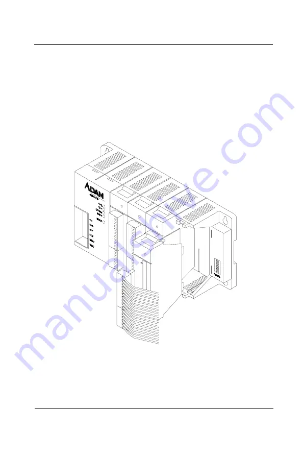
2.2 Module Installation
When inserting modules into the system, align the PC board of the
module with the grooves on the top and bottom of the system. Push
the module straight into the system until it is firmly seated in the
backplane connector. Once the module is inserted into the system,
push in the retaining clips (located at the top and bottom of the
module) to firmly secure the module to the system.
Figure 2-4:
Module alignment and installation
Содержание ADAM-5510/P31
Страница 17: ...0 Quick Start...
Страница 38: ...0 22 ADAM 5510 P31 Quick Start...
Страница 39: ...1 Introduction...
Страница 43: ...2 Installation Guidelines...
Страница 52: ...2 10 ADAM 5510 P31 Installation Guideline Figure 2 10 ADAM 5510 P31 network address DIP switch...
Страница 58: ...2 16 ADAM 5510 P31 Installation Guideline...
Страница 59: ...3 System Specifications...
Страница 65: ...4 I O Modules...
Страница 116: ...4 52 ADAM 5510 P31 I O Modules...
Страница 117: ...ADAM 5510 P31 5 1 Chapter 5 5 Troubleshooting...
Страница 129: ...ADAM 5510 P31 A 1 Appendix A A Quick Start Example...
Страница 132: ...A 4 ADAM 5510 P31 Quick Start Example...
Страница 133: ...ADAM 5510 P31 B 1 Appendix B B COM Port Register Structure...
Страница 137: ...ADAM 5510 P31 C 1 Appendix C C Data Formats and I O Ranges...
Страница 147: ...D Performance...
Страница 173: ...E RS 485 Network...
Страница 181: ...ADAM 5510 P31 F 1 Appendix F F ADAM 4000 5000 System Grounding Installation...
Страница 187: ...ADAM 5510 P31 G 1 Appendix G G Grounding Reference...
Страница 202: ...G 16 ADAM 5510 P31 Grounding Reference...


