background image

S

WITCH

 I

NSTALLATION

40

2.4.1 Installing SFP Modules

To connect the fiber transceiver and LC cable, use the following guidelines:

1.

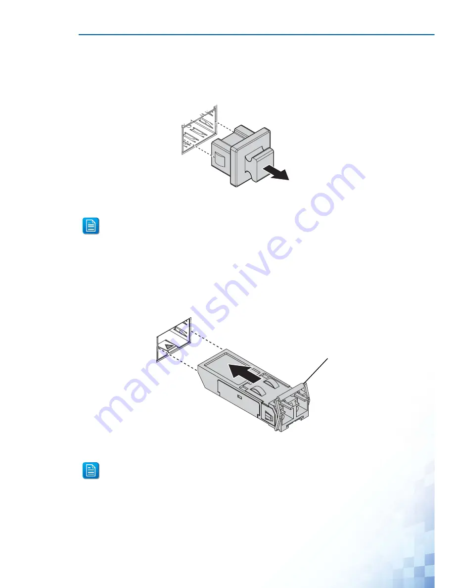
Remove the dust plug from the fiber optic slot chosen for the SFP transceiver.

Figure 2-6.

Removing the Dust Plug from an SFP Slot

2.

Position the SFP transceiver with the handle on top, see the following figure.

3.

Locate the triangular marking in the slot and align it with the bottom of the transceiver.

4.

Insert the SFP transceiver into the slot until it clicks into place.

5.

Make sure the module is seated correctly before sliding the module into the slot. A click 
sounds when it is locked in place.

Figure 2-7.

Installing an SFP Transceiver

Do not remove the dust plug from the SFP slot if you are not installing the trans-
ceiver at this time. The dust plug protects hardware from dust contamination.

If you are attaching fiber optic cables to the transceiver, continue with the following 
step. Otherwise, repeat the previous steps to install the remaining SFP transceivers 
in the device.

Handle

Содержание EKI-5000 Series

Страница 1: ...User Manual EKI 5000 Series ProView Series Ethernet Switches P N 2015 EKI 5000 01 Version Edition 4 2015 06 ...

Страница 2: ... Switch 36 2 3 1 DIN Rail Mounting 36 2 3 2 Wall Mounting 37 2 4 Installing and Removing SFP Modules 39 2 4 1 Installing SFP Modules 40 2 4 2 Removing SFP Modules 41 2 5 Connecting the Switch to Ethernet Ports 42 2 5 1 RJ45 Ethernet Cable Wiring 42 2 6 Power Supply Installation 43 2 6 1 Overview 43 2 6 2 Considerations 43 2 6 3 Grounding the Device 44 2 6 4 Wiring a Relay Contact 45 2 6 5 Wiring t...

Страница 3: ...7 3 7 TreeView 57 3 8 Information Panel 57 3 9 Status Bar 57 3 10 Configuration Area 57 Chapter 4 Managing Switch 4 1 Discovering Switches 59 4 1 1 First Time Installation 59 4 1 2 Discovering Switches 61 4 1 3 Group Management 62 4 1 4 Configuring the System 67 4 2 Modbus TCP Mapping 70 4 2 1 Modbus TCP Mapping Table 71 ...

Страница 4: ...cy energy and if not installed and used in accordance with the instruction manual may cause harmful interference to radio communications Operation of this equipment in a residential area is likely to cause harmful interference in which case the user will be required to correct the interference at his own expense Warnings for Class 1 Division 2 The following statements are required to appear for Cl...

Страница 5: ... liquid or spray detergents for cleaning For plug in equipment the power outlet socket must be located near the equipment and must be easily accessible Keep this equipment away from humidity Put this equipment on a reliable surface during installation Dropping it or letting it fall may cause danage The openings on the enclosure are fo air convection Protect the equipment from over heating DO NOT C...

Страница 6: ... original purchaser that each of its products will be free from defects in materials and workmanship for five years from the date of purchase This warranty does not apply to any products which have been repaired or altered by per sons other than repair personnel authorized by Advantech or which have been subject to misuse abuse accident or improper installation Advantech assumes no liability under...

Страница 7: ...vice 5 Write the RMA number visibly on the outside of the package and ship it prepaid to your dealer Conventions Copyright Copyright 2015 Advantech Inc All rights reserved No part of this publication may be reproduced adapted stored in a retrieval system translated into any language or transmit ted in any form or by any means without the written permission of the manufacturer Warning signs are use...

Страница 8: ...dy before you call Product name and serial number Description of your peripheral attachment Description of your software operating system version application software etc A complete description of the problem The exact wording of any error messages About This Manual This user manual is intended to guide professional installers in installing and configuring the ProView Series Ethernet Switches It i...

Страница 9: ...Chapter 1 Product Overview ...

Страница 10: ...T EKI 5525 EKI 5725 EKI 5728 EKI 5729F EKI 5725FP EKI 5528 EKI 5526 EKI 5726 EKI 5726F EKI 5629C EKI 5626C EKI 5624P EKI 5729P Table 1 2 Wide Temperature Models EKI 5525SI EKI 5525MI EKI 5525SI ST EKI 5525MI ST EKI 5524SSI EKI 5524MMI EKI 5524SSI ST EKI 5524MMI ST EKI 5525I EKI 5725I EKI 5728I EKI 5729FI EKI 5725FPI EKI 5528I EKI 5526I EKI 5726I EKI 5726FI EKI 5629CI EKI 5626CI EKI 5624PI EKI 5729...

Страница 11: ...725I 5 x 10 100 1000BaseT X EKI 5728 EKI 5728I 8 x 10 100 1000BaseT X EKI 5729F EKI 5729FI 8 x 10 100 1000BaseT X 2 x 100 1000Base FX SFP EKI 5725FP EKI 5725FPI 4 x 10 100 1000BaseT X with PoE 1 x 100 1000Base FX SFP EKI 5528 EKI 5528I 8 x 10 100BaseT X EKI 5526 EKI 5526I 16 x 10 100BaseT X EKI 5726 EKI 5726I 16 x 10 100 1000BaseT X EKI 5726F EKI 5726FI 16 x 10 100 1000BaseT X 2 x 100 1000Base FX ...

Страница 12: ...mm x 84mm EKI 5725 EKI 5725I 27mm x 120mm x 84mm EKI 5728 EKI 5728I 43mm x 120mm x 84mm EKI 5729F EKI 5729FI 43mm x 120mm x 84mm EKI 5725FP EKI 5725FPI 74mm x 152mm x 105mm EKI 5528 EKI 5528I 43mm x 120mm x 84mm EKI 5526 EKI 5526I 74mm x 120mm x 84mm EKI 5726 EKI 5726I 74mm x 120mm x 84mm EKI 5726F EKI 5726FI 74mm x 120mm x 84mm EKI 5629C EKI 5629CI 74mm x 120mm x 84mm EKI 5626C EKI 5626CI 74mm x ...

Страница 13: ...T 2K entries EKI 5524SS EKI 5524SSI 2K entries EKI 5524MM EKI 5524MMI 2K entries EKI 5524SS ST EKI 5524SSI ST 2K entries EKI 5524MM ST EKI 5524MMI ST 2K entries EKI 5525 EKI 5525I 2K entries EKI 5725 EKI 5725I 2K entries EKI 5728 EKI 5728I 8K entries EKI 5729F EKI 5729FI 8K entries EKI 5725FP EKI 5725FPI 2K entries EKI 5528 EKI 5528I 8K entries EKI 5526 EKI 5526I 8K entries EKI 5726 EKI 5726I 8K e...

Страница 14: ...1 2 Gbps EKI 5524MM ST EKI 5524MMI ST 1 2 Gbps EKI 5525 EKI 5525I 1 Gbps EKI 5725 EKI 5725I 10 Gbps EKI 5728 EKI 5728I 16 Gbps EKI 5729F EKI 5729FI 20 Gbps EKI 5725FP EKI 5725FPI 10 Gbps EKI 5528 EKI 5528I 1 6 Gbps EKI 5526 EKI 5526I 3 2 Gbps EKI 5726 EKI 5726I 32 Gbps EKI 5726F EKI 5726FI 36 Gbps EKI 5629C EKI 5629CI 5 6 Gbps EKI 5626C EKI 5626CI 7 2 Gbps EKI 5624P EKI 5624PI 4 8Gbps EKI 5729P EK...

Страница 15: ...s EKI 5728 EKI 5728I 5 2 watts EKI 5729F EKI 5729FI 6 8 watts EKI 5725FP EKI 5725FPI 89 watts EKI 5528 EKI 5528I 3 6 watts EKI 5526 EKI 5526I 3 84 watts EKI 5726 EKI 5726I 8 watts EKI 5726F EKI 5726FI 9 6 watts EKI 5629C EKI 5629CI 5 8 watts EKI 5626C EKI 5626CI 8 2 watts EKI 5624P EKI 5624PI 60 watts EKI 5729P EKI 5729PI 65 watts Power Input 12V 48V 8 4V 52 8V redundant dual inputs 24V 48V 16 8V ...

Страница 16: ...I 5728 EKI 5728I EKI 5729F EKI 5729FI EMI EN 55011 55022 Class A EN 61000 6 4 FCC Part 15 Subpart B Class A EMS EN 55024 EN 61000 6 2 EN 61000 4 2 ESD Level 3 EN 61000 4 3 RS Level 3 EN 61000 4 4 EFT Level 3 EN 61000 4 5 Surge Level 3 EN 61000 4 6 CS Level 3 EN 61000 4 8 Magnetic Field Level 3 Shock IEC 60068 2 27 Freefall IEC 60068 2 32 Vibration IEC 60068 2 6 Table 1 3 Specifications Continued S...

Страница 17: ...iew No Item Description 1 System LED panel See System LED Panel on page 22 for further details 2 ETH port EKI 5525 EKI 5525I Four 10 100BaseT X ports EKI 5725 EKI 5725I Four 10 100 1000BaseT X ports Port numbers in black are designated for port based Quality of Ser vice QoS functionality 3 LNK ACT LED Link activity LED 3 4 5 P2 P1 P Fail Loop 1 2 EKI 5725 1 2 5 3 4 ...

Страница 18: ...0M Off 10M Fast Ethernet Amber 100M Off 10M 5 ETH port EKI 5525 EKI 5525I One 10 100BaseT X port EKI 5725 EKI 5725I One 10 100 1000BaseT X port Table 1 5 Front View No Item Description 1 System LED panel See System LED Panel on page 22 for further details Table 1 4 Front View Continued No Item Description P2 P1 P Fail Loop 8 7 6 5 3 4 1 2 EKI 5528 5528I 1 2 3 4 ...

Страница 19: ...black are designated for port based Quality of Ser vice QoS functionality 3 LNK ACT LED Link activity LED 4 Speed LED Gigabit Ethernet Green 1000M Amber 100M Off 10M Fast Ethernet Amber 100M Off 10M Table 1 6 Front View No Item Description 1 System LED panel See System LED Panel on page 22 for further details Table 1 5 Front View Continued No Item Description P2 P1 P Fail Loop 8 7 6 5 3 4 10 9 1 2...

Страница 20: ...ink activity LED 4 Speed LED Gigabit Ethernet Green 1000M Amber 100M Off 10M 5 ETH port Two 100 1000Base FX SFP ports Table 1 7 Front View No Item Description 1 System LED panel See System LED Panel on page 22 for further details 2 ETH port Four RJ45 ports Port numbers in black are designated for port based Quality of Ser vice QoS functionality Table 1 6 Front View Continued No Item Description 3 ...

Страница 21: ...single mode port EKI 5525M EKI 5525MI One SC multi mode port Table 1 8 Front View No Item Description 1 System LED panel See System LED Panel on page 22 for further details 2 ETH port Four RJ45 ports Port numbers in black are designated for port based Quality of Ser vice QoS functionality 3 LNK ACT LED Link activity LED Table 1 7 Front View Continued No Item Description 3 4 5 P2 P1 P Fail Loop 1 2...

Страница 22: ...5M ST EKI 5525MI ST One ST multi mode port Table 1 9 Front View No Item Description 1 System LED panel See System LED Panel on page 22 for further details 2 ETH port Four RJ45 ports Port numbers in black are designated for port based Quality of Ser vice QoS functionality 3 LNK ACT LED Link activity LED Table 1 8 Front View Continued No Item Description P2 P1 P Fail Loop EKI 5524SSI 5524SSI 3 4 5 1...

Страница 23: ...5524MM EKI 5524MMI Two SC multi mode ports Table 1 10 Front View No Item Description 1 System LED panel See System LED Panel on page 22 for further details 2 ETH port Four RJ45 ports Port numbers in black are designated for port based Quality of Ser vice QoS functionality 3 LNK ACT LED Link activity LED Table 1 9 Front View Continued No Item Description P2 P1 P Fail Loop EKI 5524SSI ST 5524SSI ST ...

Страница 24: ...rts Table 1 11 Front View No Item Description 1 System LED panel See System LED Panel on page 22 for further details 2 ETH port EKI 5526 EKI 5526I Sixteen 10 100BaseT X ports EKI 5726 EKI 5726I Sixteen 10 100 1000BaseT X ports Port numbers in black are designated for port based Quality of Ser vice QoS functionality 3 LNK ACT LED Link activity LED Table 1 10 Front View Continued No Item Description...

Страница 25: ...m LED Panel on page 22 for further details 2 ETH port Eight 10 100BaseT X ports Port numbers in black are designated for port based Quality of Ser vice QoS functionality 3 LNK ACT LED Link activity LED 4 Speed LED Fast Ethernet Amber 100M Off 10M 5 ETH port Two 10 100 1000BaseT X ports Table 1 11 Front View Continued No Item Description P2 P1 P Fail Loop 8 7 6 5 10 9 3 4 1 2 EKI 5629C 5629C 9 10 1...

Страница 26: ...ther details 2 ETH port Sixteen 10 100BaseT X ports Port numbers in black are designated for port based Quality of Ser vice QoS functionality 3 LNK ACT LED Link activity LED 4 Speed LED Fast Ethernet Amber 100M Off 10M 5 ETH port Two 10 100 1000BaseT X ports 6 ETH port Two 100 1000Base FX SFP ports Table 1 12 Front View Continued No Item Description P2 P1 P Fail Loop 8 7 6 5 12 11 10 9 16 17 18 15...

Страница 27: ... page 22 for further details 2 ETH port Sixteen 10 100 1000BaseT X ports Port numbers in black are designated for port based Quality of Ser vice QoS functionality 3 LNK ACT LED Link activity LED 4 Speed LED Gigabit Ethernet Green 1000M Amber 100M Off 10M 5 ETH port Two 100 1000Base FX SFP ports P2 P1 P Fail Loop 8 7 6 5 12 11 10 9 16 15 14 13 3 4 18 17 1 2 EKI 5726F 726F 1 2 5 3 4 ...

Страница 28: ...eT X with PoE ports 2 LNK ACT LED Link activity LED 3 Speed LED Gigabit Ethernet Green 1000M Amber 100M Off 10M 4 ETH port One 100 1000Base FX SFP port 5 System LED panel See System LED Panel only for EKI 5725FP EKI 5725FPI EKI 5624P EKI 5624PI and EKI 5729P EKI 5729PI on page 23 for fur ther details P1 P2 P Fail Loop PoE 1 2 3 4 3 4 1 2 EKI 5725FP 5FP 5 LNK ACT 5 1 2 3 4 ...

Страница 29: ...100 1000BaseT X ports 2 ETH port Four 10 100BaseT X with PoE ports 3 LNK ACT LED Link activity LED 4 Speed LED Fast Ethernet Amber 100M Off 10M 5 System LED panel See System LED Panel only for EKI 5725FP EKI 5725FPI EKI 5624P EKI 5624PI and EKI 5729P EKI 5729PI on page 23 for fur ther details EKI 5624PI 4PI 6 5 P1 P2 P Fail Loop PoE 1 2 3 4 3 4 1 2 5 2 3 4 1 ...

Страница 30: ...ts 2 ETH port Eight 10 100 1000BaseT X with PoE ports 3 LNK ACT LED Link activity LED 4 Speed LED Gigabit Ethernet Green 1000M Amber 100M Off 10M 5 System LED panel See System LED Panel only for EKI 5725FP EKI 5725FPI EKI 5624P EKI 5624PI and EKI 5729P EKI 5729PI on page 23 for fur ther details EKI 5729PI 9PI 8 7 6 5 3 4 10 9 1 2 P1 P2 P Fail Loop PoE 1 2 3 4 5 6 7 8 5 2 3 4 1 ...

Страница 31: ...D Solid green Powered up Off Powered down or not installed 2 PW2 LED Solid green Powered up Off Powered down or not installed 3 P Fail Solid red When PW1 or PW2 is disconnected the LED lights Off When PW1 and PW2 is connected the LED is off 4 Loop Solid red When loop detected the LED lights Off No loop detected P2 P1 P Fail Loop 1 2 3 4 ...

Страница 32: ...Solid green Powered up Off Powered down or not installed 3 P Fail Solid red When PW1 or PW2 is disconnected the LED lights Off When PW1 and PW2 is connected the LED is off 4 Loop Solid red When loop detected the LED lights Off No loop detected 5 PoE depending the PoE ports Solid green PoE activated Off PoE non working SFP only for EKI 5725FP EKI 5725FPI Solid green SFP activated Blinking Data is b...

Страница 33: ...I 5525SI EKI 5525M EKI 5525MI EKI 5525S ST EKI 5525SI ST EKI 5525M ST EKI 5525MI ST EKI 5525 EKI 5525I EKI 5725 and EKI 5725I Figure 1 17 Rear View Table 1 20 Rear View No Item Description 1 DIN Rail mounting plate Mounting plate used for the installation to a standard DIN rail 1 ...

Страница 34: ...29FI EKI 5528 EKI 5528I EKI 5524SS EKI 5524SSI EKI 5524MM EKI 5524MMI EKI 5524SS ST EKI 5524SSI ST EKI 5524MM ST and EKI 5524MMI ST Figure 1 18 Rear View Table 1 21 Rear View No Item Description 1 DIN Rail mounting plate Mounting plate used for the installation to a standard DIN rail 1 ...

Страница 35: ...5526 EKI 5526I EKI 5629C EKI 5629CI EKI 5626C EKI 5626CI EKI 5726 EKI 5726I EKI 5726F and EKI 5726FI Figure 1 19 Rear View Table 1 22 Rear View No Item Description 1 DIN Rail mounting plate Mounting plate used for the installation to a standard DIN rail 1 ...

Страница 36: ...ew applies to EKI 5725FP EKI 5725FPI EKI 5624P EKI 5624PI EKI 5729P and EKI 5729PI Figure 1 20 Rear View Table 1 23 Rear View No Item Description 1 DIN Rail mounting plate Mounting plate used for the installation to a standard DIN rail 1 ...

Страница 37: ...728I EKI 5729F EKI 5729FI EKI 5528 EKI 5528I EKI 5524SS EKI 5524SSI EKI 5524MM EKI 5524MMI EKI 5524SS ST EKI 5524SSI ST EKI 5524MM ST and EKI 5524MMI ST Figure 1 22 Top View Table 1 24 Top View No Item Description 1 Terminal block Connect cabling for power and alarm wiring Table 1 25 Top View No Item Description 1 Terminal block Connect cabling for power and alarm wiring P Fail V2 PWR2 DC 12 48V 1...

Страница 38: ... to EKI 5726 EKI 5726I EKI 5726I and EKI 5726FI Figure 1 24 Top View Table 1 26 Top View No Item Description 1 Terminal block Connect cabling for power and alarm wiring Table 1 27 Top View No Item Description 1 Terminal block Connect cabling for power and alarm wiring P Fail V2 PWR2 DC 12 48V 1A 24V PWR1 V2 V1 V1 1 P Fail V2 PWR2 DC 12 48V 1A 24V PWR1 V2 V1 V1 1 ...

Страница 39: ...P EKI 5624PI EKI 5729P and EKI 5729PI Figure 1 26 Top View Table 1 28 Top View No Item Description 1 Terminal block Connect cabling for power and alarm wiring Table 1 29 Top View No Item Description 1 Terminal block Connect cabling for power and alarm wiring P Fail V2 PWR2 DC24 48V PWR1 V2 V1 V1 1 P Fail V2 PWR2 DC12 24V PWR1 V2 V1 V1 1 ...

Страница 40: ...View The following view applies to EKI 5728 EKI 5728I EKI 5729F EKI 5729FI EKI 5528 EKI 5528I EKI 5524SS EKI 5524SSI EKI 5524MM EKI 5524MMI EKI 5524SS ST EKI 5524SSI ST EKI 5524MM ST and EKI 5524MMI ST Figure 1 28 Bottom View Table 1 30 Bottom View No Item Description 1 Ground terminal Screw terminal used to ground chassis Table 1 31 Bottom View No Item Description 1 Ground terminal Screw terminal...

Страница 41: ...EKI 5626CI EKI 5726 EKI 5726I EKI 5726F and EKI 5726FI Figure 1 29 Bottom View The following view applies to EKI 5725FP EKI 5725FPI EKI 5624P EKI 5624PI EKI 5729P and EKI 5729PI Figure 1 30 Bottom View Table 1 32 Bottom View No Item Description 1 Ground terminal Screw terminal used to ground chassis 1 ...

Страница 42: ...uld contain the following items If any of them are not included or damaged please contact your local vendor for support 1 x Industrial Ethernet Switch 1 x Wall mounting Bracket 1 x DIN Rail mounting Bracket and Screws 1 x EKI Device Configuration Utility CD ROM 1 x Startup Manual ...

Страница 43: ...Chapter 2 Switch Installation ...

Страница 44: ...oper airflow the switch can overheat To prevent performance degredation and dam age to the switch make sure there is clerance at the top and bottom and around the exhaust vents 2 1 1 Connecting Hardware In this instruction it will explain how to find a proper location for your Modbus Gateways and how to connect to the network hock up the power cable and connect to the EKI 5000 Series 2 2 Verifying...

Страница 45: ...mm 3 height DIN rail The devices can be mounted vertically or horizontally Refer to the following guidelines for further information Installing the DIN Rail Mounting Kit 1 Insert the top back of the mounting bracket over the DIN rail 2 Push the bottom of the switch towards the DIN rail until it snaps into place Figure 2 1 Installing the DIN Rail Mounting Kit A corrosion free mounting rail is advis...

Страница 46: ...istance than the DIN rail vertical mount Before the device can be mounted on a wall you will need to remove the DIN rail plate 1 Rotate the device to the rear side and locate the DIN mounting plate 2 Remove the screws securing the DIN mounting plate to the rear panel of the switch 3 Remove the DIN mounting plate Store the DIN mounting plate and provided screws for later use 4 Align the wall mounti...

Страница 47: ...es over the four marked locations on the wall keeping in mind that the holes must accommodate wall sinks in addition to the screws 9 Insert the wall sinks into the walls 10 Insert the screws into the wall sinks Leave a 2 mm gap between the wall and the screw head to allow for wall mount plate insertion Figure 2 4 Securing Wall Mounting Screws 11 Align the wall mount plate over the screws on the wa...

Страница 48: ...ement The concept behind the LC port and cable is quite straight forward Suppose that you are connecting devices I and II contrary to electrical signals optical signals do not require a cir cuit in order to transmit data Consequently one of the optical lines is used to transmit data from device I to device II and the other optical line is used transmit data from device II to device I for full dupl...

Страница 49: ...tom of the transceiver 4 Insert the SFP transceiver into the slot until it clicks into place 5 Make sure the module is seated correctly before sliding the module into the slot A click sounds when it is locked in place Figure 2 7 Installing an SFP Transceiver Do not remove the dust plug from the SFP slot if you are not installing the trans ceiver at this time The dust plug protects hardware from du...

Страница 50: ...vers in the switch The fiber port is now setup 2 4 2 Removing SFP Modules To disconnect an LC connector use the following guidelines 1 Press down and hold the locking clips on the upper side of the optic cable 2 Pull the optic cable out to release it from the transceiver Figure 2 9 Removing a Fiber Optic Cable to a Transceiver Do not remove the dust plug from the transceiver if you are not install...

Страница 51: ...d connected to the GND terminal For best performance use shielded cabling Shielded cabling may be used to provide further protection Figure 2 11 Ethernet Plug Connector Pin Position Maximum cable length 100 meters 328 ft for 10 100 1000BaseT Replace the dust plug on the slot if you are not installing a transceiver The dust plug protects hardware from dust contamination Table 2 1 RJ45 Ethernet Wiri...

Страница 52: ...lowing guidelines before wiring the device The Terminal Block CN1 is suitable for 12 24 AWG 3 31 0 205 mm2 Torque value 7 lb in The cross sectional area of the earthing conductors shall be at least 3 31 mm2 Calculate the maximum possible current for each power and common wire Make sure the power draw is within limits of local electrical code regulations For best practices route wiring for power an...

Страница 53: ...terference To avoid interference and signal degradation route power and communications wires through separate conduits Do not disconnect modules or cabling unless the power is first switched off The device only supports the voltage outlined in the type plate Do not use any other power components except those specifically designated for the switch device Before connecting the device properly ground...

Страница 54: ...s The power input 2 is used for wiring a redundant power configuration See the following for terminal block connector views Figure 2 15 Terminal Receptor Power Input Contacts Before applying power to the grounded switch it is advisable to use a volt meter to ensure there is no voltage difference between the power supply s negative output terminal and the grounding point on the switch Do not discon...

Страница 55: ... the V1 V1 wire clamp screws and loosen the screws 4 Insert the negative positive DC wires into the V V terminals of PW1 If setting up power redundancy connect PW2 in the same manner 5 Tighten the wire clamp screws to secure the DC wires in place Figure 2 17 Installing DC Wires in a Terminal Block 6 Align the terminal block over the terminal block receptor on the switch 7 Insert the terminal block...

Страница 56: ...e screws on the terminal block to secure it to the terminal block receptor If there is no gap between the terminal block and the terminal receptor the terminal block is seated correctly Figure 2 18 Securing a Terminal Block to a Receptor ...

Страница 57: ...Chapter 3 Configuration Utility ...

Страница 58: ...continuing further any devices selected for configuration must be connected and powered on see Installation Guidelines on page 35 1 From your Windows desktop locate the Start button to open the Start Menu 2 Navigate to All Programs EKI Device Configuration Utility 3 Locate Advantech EKI Device Configuration Utility and right click on it From the pop up menu select Run as Administrator See your net...

Страница 59: ...ity CD ROM into the CD ROM drive whereas E is the drive name of your CD ROM on the host PC 2 Use Windows explorer or the Windows Run command to execute the setup program the path for the setup program on the CD ROM is as follows E EKI_Device_Configuration_Utility_v1 70 exe 3 If there is an existing COM port mapping utility on the host PC remove it at this time A system reboot may be necessary befo...

Страница 60: ...d Wizard screen displays click Next to proceed with the installa tion Figure 3 2 InstallShield Wizard 1 of 4 5 The Software License Agreement displays press I Agree to continue or Cancel to stop the installation Figure 3 3 InstallShield Wizard 2 of 4 ...

Страница 61: ...on path is C Program Files EKI Device Configuration Utility Figure 3 4 InstallShield Wizard 3 of 4 6 Once the installation of the package is finished a Configuration Utility Setup screen dis plays Click Finish to conclude the process and exit the InstallShield Wizard Figure 3 5 InstallShield Wizard 4 of 4 ...

Страница 62: ...ity Overview Table 3 1 Configuration Utility Overview No Item Description 1 Menu Bar Displays File View Management Tools and Help 2 Tool Bar Useful management functions shortcuts 3 Tree View All devices will be searched and listed in this area You can arrange different favorite group and virtual COM ports 4 Information Panel Click on the devices or move cursor to the devices the related informatio...

Страница 63: ...ttings Maximum Main Window On Load Check the box to enable the limiting of main windows on load to the maximum value Log Settings Show Log Message Window Check the checkbox to show the log message Save Log to File Check the checkbox to save log to file Browse Click Browse to choose a file to save Language Settings Interface Language Click the drop down menu to select an interface language Traditio...

Страница 64: ...e or disable grouping Show Empty Device Type Node Check the checkbox to show empty device type node or not Expand New Appended Device Node Check the checkbox to expand a new appended device node or not Device Auto Detection After utility ready start auto detection after X second Enter a value to specify the time to auto detection time 1 means disable auto detection Auto detect devices every X seco...

Страница 65: ... Description Configuration Wizard Start the software wizard setup assistant to leads you through the VCOM configuration process for device server product Clear Device List and Search Again Clear all device list and re search devices Search Again Re search devices Add IP Address to Favorite Add one device to Favorites Search for a Range of IP Addresses Add a group of device to Favorites Manual Dire...

Страница 66: ...page 53 3 9 Status Bar The Status Bar area displays the current time See Utility Menu Map on page 53 3 10 Configuration Area The Configuration Area displays correlating information from selected menu items within the TreeView area See Utility Menu Map on page 53 Table 3 6 Tool Bar Icon Item Description Utility Settings Refer to Utility Settings on page 54 Configuration Wizard Refer to Management M...

Страница 67: ...Chapter 4 Managing Switch ...

Страница 68: ...vides two ways to configure network settings DHCP Auto IP Settings or Static Settings DHCP Auto IP Settings 1 Select Ethernet under the desired device 2 Click the drop down menu to select DHCP Auto IP 3 Click Apply to confirm the settings Figure 4 1 Selecting Networking Setting Static Settings 1 Select Ethernet under the desired device 2 Click the drop down menu to select Static IP 3 Enter the IP ...

Страница 69: ...MANAGING SWITCH 60 4 Click Apply to confirm the settings Figure 4 2 Configuring a Static IP Setting ...

Страница 70: ...hes Auto Search Only devices within the same network domain can be listed through the search function Once a device is listed the features and configuration details are accessible by clicking on the device name Figure 4 3 Auto Searching Screen ...

Страница 71: ...listing of the devices You can use the Search function again to detect any devices connected to the network domain 4 1 3 Group Management Creating Groups Groups are best used to identify a set of devices with a common characteristic and to better organize the device pool To create a favorite group please follow the instructions as follows 1 Right click Favorite to display the settings 2 Select Cre...

Страница 72: ...MANAGING SWITCH 63 3 Enter a group name and click OK Figure 4 5 Adding a Group The group is created and is available in the Favorite s List ...

Страница 73: ...ice selecting an IP address and selecting an IP address range The following guidelines allow you to create a favorite s list Adding a Device 1 Right click a desired device to display the settings menu 2 Select Add to Favorite Figure 4 6 Adding a Switch to Favorites In the event that there are existing groups you can select the specific favorite group to include the selected device ...

Страница 74: ...ck the Add IP Address to Favorite button 2 Enter an IP address 3 Click OK to add the IP address into the favorites list Figure 4 7 Add Favorite In the event that there are existing groups you can select the specific favorite group to include the selected IP address ...

Страница 75: ...for a Range of IP Addresses button 2 Enter a starting and ending IP address range 3 Click OK to add the range into the favorites list Figure 4 8 Add Favorite In the event that there are existing groups you can select the specific favorite group to include the selected IP address range ...

Страница 76: ...to configure the device Figure 4 9 Changing Device Name The device name is changed Setting Modbus TCP Idle Time 1 Select the device to configure by clicking on it 2 In the Configuration Area select the System tab 3 Locate the Modbus TCP Host Idle Time s field 4 Enter a variable representing the idle time for the Modbus TCP host function ProView provides the following information to SCADA through M...

Страница 77: ...atus Port Speed Flow Control Port Description Link Up Counter PoE Status Tx Packets Counter Rx Packets Counter Tx Error Packets Counter Rx Error Packets Counter 5 Click Apply to configure the function Figure 4 10 Setting Modbus TCP Idle Time The Modbus TCP idle time is now set ...

Страница 78: ...information Setting Networks Parameters For setting networks parameters see Configuring Network Settings on page 59 Setting SNMP 1 Select the device to configure by clicking on it 2 In the Configuration Area select SNMP tab The Basic and Community settings are listed for configuration 3 In the SNMP Basic Settings selection enter a contact and location in the respective fields 4 In the SNMP Communi...

Страница 79: ...he PoE function on the port click on the radio box to unselect it 4 Click Refresh to update the PoE status for each port Each port displays the current enabled or disabled state in addition to the following information Voltage V Current mA Power W Temperature Celsius Figure 4 12 Setting Modbus TCP Idle Time 4 2 Modbus TCP Mapping The data map addresses of Advantech switches shown in the following ...

Страница 80: ...en by the Advantech is shown in hex mode 4 2 1 Modbus TCP Mapping Table Table 4 1 Modbus TCP Mapping Table Catelog Name Data Type Inter preta tion Address Offset Hex Address 3X Description System Info Vendor ID 0x 13FE 1 word 16 bits HEX 0x0000 30001 Vendor ID 0x13FE Unit ID 0xFF 1 word 16 bits HEX 0x0001 30002 Unit ID 0xFF Product Code 1 word 16 bits HEX 0x0002 30003 Product Code ...

Страница 81: ...i byte I Word 1 Lo byte Word 2 Hi byte x Word 2 Lo byte x Word 3 Hi byte x Word 3 Lo byte x Word 4 Hi byte 0 Firmware Version 2 words 32 bits HEX 0x020A 30523 Firmware Version Word 0 Hi byte major Word 0 Lo byte minor Word 1 Hi byte release Word 1 Lo byte build Ethernet MAC Address 3 words 48 bits HEX 0x020E 30527 Ethernet MAC Address Ex MAC 00 19 CB 01 02 03 Word 0 Hi byte 0x00 Word 0 Lo byte 0x1...

Страница 82: ... down 0x0001 Link up 0xFFFF No port Port 1 Status 1 word 16 bits HEX 0x1000 34097 Port 2 Status 1 word 16 bits HEX 0x1001 34098 Port 3 Status 1 word 16 bits HEX 0x1002 34099 Port 4 Status 1 word 16 bits HEX 0x1003 34100 Port 5 Status 1 word 16 bits HEX 0x1004 34101 Port 6 Status 1 word 16 bits HEX 0x1005 34102 Port 7 Status 1 word 16 bits HEX 0x1006 34103 Port 8 Status 1 word 16 bits HEX 0x1007 34...

Страница 83: ...117 Port 22 Sta tus 1 word 16 bits HEX 0x1015 34118 Port 23 Sta tus 1 word 16 bits HEX 0x1016 34119 Port 24 Sta tus 1 word 16 bits HEX 0x1017 34120 Port 25 Sta tus 1 word 16 bits HEX 0x1018 34121 Port 26 Sta tus 1 word 16 bits HEX 0x1019 34122 Port 27 Sta tus 1 word 16 bits HEX 0x101A 34123 Port 28 Sta tus 1 word 16 bits HEX 0x101B 34124 Port 29 Sta tus 1 word 16 bits HEX 0x101C 34125 Port 30 Sta ...

Страница 84: ...d 16 bits HEX 0x1106 34359 Port 8 Speed 1 word 16 bits HEX 0x1107 34360 Port 9 Speed 1 word 16 bits HEX 0x1108 34361 Port 10 Speed 1 word 16 bits HEX 0x1109 34362 Port 11 Speed 1 word 16 bits HEX 0x110A 34363 Port 12 Speed 1 word 16 bits HEX 0x110B 34364 Port 13 Speed 1 word 16 bits HEX 0x110C 34365 Port 14 Speed 1 word 16 bits HEX 0x110D 34366 Port 15 Speed 1 word 16 bits HEX 0x110E 34367 Port 16...

Страница 85: ...word 16 bits HEX 0x111C 34381 Port 30 Speed 1 word 16 bits HEX 0x111D 34382 Port 31 Speed 1 word 16 bits HEX 0x111E 34383 Port 32 Speed 1 word 16 bits HEX 0x111F 34384 Flow Control 1 word 16 bits HEX 0x1200 0x121F 34609 34640 Flow Control 0x0000 Off 0x0001 On 0xFFFF No port Port 1 Flow Control 1 word 16 bits HEX 0x1200 34609 Port 2 Flow Control 1 word 16 bits HEX 0x1201 34610 Port 3 Flow Control 1...

Страница 86: ...t 15 Flow Control 1 word 16 bits HEX 0x120E 34623 Port 16 Flow Control 1 word 16 bits HEX 0x120F 34624 Port 17 Flow Control 1 word 16 bits HEX 0x1210 34625 Port 18 Flow Control 1 word 16 bits HEX 0x1211 34626 Port 19 Flow Control 1 word 16 bits HEX 0x1212 34627 Port 20 Flow Control 1 word 16 bits HEX 0x1213 34628 Port 21 Flow Control 1 word 16 bits HEX 0x1214 34629 Port 22 Flow Control 1 word 16 b...

Страница 87: ...121 35741 Port Description Port Description 100RX RJ45 Word 0 Hi byte 1 Word 0 Lo byte 0 Word 1Hi byte 0 Word 1 Lo byte R Word 2 Hi byte X Word 2 Lo byte Word 3 Hi byte R Word 3 Lo byte J Word 4 Hi byte 4 Word 4 Lo byte 5 Word 5 Hi byte Word 5 Lo byte 0 Port 1 Description 20 words 40 chars ASCII 0x1400 35121 Port 2 Description 20 words 40 chars ASCII 0x1414 35141 Port 3 Description 20 words 40 cha...

Страница 88: ... Description 20 words 40 chars ASCII 0x1518 35401 Port 16 Description 20 words 40 chars ASCII 0x152C 35421 Port 17 Description 20 words 40 chars ASCII 0x1540 35441 Port 18 Description 20 words 40 chars ASCII 0x1554 35461 Port 19 Description 20 words 40 chars ASCII 0x1568 35481 Port 20 Description 20 words 40 chars ASCII 0x157C 35501 Port 21 Description 20 words 40 chars ASCII 0x1590 35521 Port 22 ...

Страница 89: ...response 0x000D Port 1 Link Up Counter 1 word 16 bits HEX 0x1700 35889 Port 2 Link Up Counter 1 word 16 bits HEX 0x1701 35890 Port 3 Link Up Counter 1 word 16 bits HEX 0x1702 35891 Port 4 Link Up Counter 1 word 16 bits HEX 0x1703 35892 Port 5 Link Up Counter 1 word 16 bits HEX 0x1704 35893 Port 6 Link Up Counter 1 word 16 bits HEX 0x1705 35894 Port 7 Link Up Counter 1 word 16 bits HEX 0x1706 35895...

Страница 90: ... 21 Link Up Counter 1 word 16 bits HEX 0x1714 35909 Port 22 Link Up Counter 1 word 16 bits HEX 0x1715 35910 Port 23 Link Up Counter 1 word 16 bits HEX 0x1716 35911 Port 24 Link Up Counter 1 word 16 bits HEX 0x1717 35912 Port 25 Link Up Counter 1 word 16 bits HEX 0x1718 35913 Port 26 Link Up Counter 1 word 16 bits HEX 0x1719 35914 Port 27 Link Up Counter 1 word 16 bits HEX 0x171A 35915 Port 28 Link...

Страница 91: ...05 36150 Port 7 PoE Voltage 1 word 16 bits HEX 0x1806 36151 Port 8 PoE Voltage 1 word 16 bits HEX 0x1807 36152 Port 9 PoE Voltage 1 word 16 bits HEX 0x1808 36153 Port 10 PoE Voltage 1 word 16 bits HEX 0x1809 36154 Port 11 PoE Voltage 1 word 16 bits HEX 0x180A 36155 Port 12 PoE Voltage 1 word 16 bits HEX 0x180B 36156 Port 13 PoE Voltage 1 word 16 bits HEX 0x180C 36157 Port 14 PoE Voltage 1 word 16 ...

Страница 92: ... PoE Voltage 1 word 16 bits HEX 0x181A 36171 Port 28 PoE Voltage 1 word 16 bits HEX 0x181B 36172 Port 29 PoE Voltage 1 word 16 bits HEX 0x181C 36173 Port 30 PoE Voltage 1 word 16 bits HEX 0x181D 36174 Port 31 PoE Voltage 1 word 16 bits HEX 0x181E 36175 Port 32 PoE Voltage 1 word 16 bits HEX 0x181F 36176 PoE Current 1 word 16 bits HEX 0x1820 0x183F 36177 36208 PoE Current mA Ex poe current 13 Recei...

Страница 93: ...t 13 PoE Current 1 word 16 bits HEX 0x182C 36189 Port 14 PoE Current 1 word 16 bits HEX 0x182D 36190 Port 15 PoE Current 1 word 16 bits HEX 0x182E 36191 Port 16 PoE Current 1 word 16 bits HEX 0x182F 36192 Port 17 PoE Current 1 word 16 bits HEX 0x1830 36193 Port 18 PoE Current 1 word 16 bits HEX 0x1831 36194 Port 19 PoE Current 1 word 16 bits HEX 0x1832 36195 Port 20 PoE Current 1 word 16 bits HEX ...

Страница 94: ...F 36208 PoE Power 1 word 16 bits HEX 0x1840 0x185F 36209 36240 PoE Power W Ex poe power 10 Received MODBUS response 0x000A Port 1 PoE Power 1 word 16 bits HEX 0x1840 36209 Port 2 PoE Power 1 word 16 bits HEX 0x1841 36210 Port 3 PoE Power 1 word 16 bits HEX 0x1842 36211 Port 4 PoE Power 1 word 16 bits HEX 0x1843 36212 Port 5 PoE Power 1 word 16 bits HEX 0x1844 36213 Port 6 PoE Power 1 word 16 bits ...

Страница 95: ...6 Port 19 PoE Power 1 word 16 bits HEX 0x1852 36227 Port 20 PoE Power 1 word 16 bits HEX 0x1853 36228 Port 21 PoE Power 1 word 16 bits HEX 0x1854 36229 Port 22 PoE Power 1 word 16 bits HEX 0x1855 36230 Port 23 PoE Power 1 word 16 bits HEX 0x1856 36231 Port 24 PoE Power 1 word 16 bits HEX 0x1857 36232 Port 25 PoE Power 1 word 16 bits HEX 0x1858 36233 Port 26 PoE Power 1 word 16 bits HEX 0x1859 3623...

Страница 96: ...ort 5 PoE Temperature 1 word 16 bits HEX 0x1864 36245 Port 6 PoE Temperature 1 word 16 bits HEX 0x1865 36246 Port 7 PoE Temperature 1 word 16 bits HEX 0x1866 36247 Port 8 PoE Temperature 1 word 16 bits HEX 0x1867 36248 Port 9 PoE Temperature 1 word 16 bits HEX 0x1868 36249 Port 10 PoE Temperature 1 word 16 bits HEX 0x1869 36250 Port 11 PoE Temperature 1 word 16 bits HEX 0x186A 36251 Port 12 PoE Te...

Страница 97: ...6 bits HEX 0x1876 36263 Port 24 PoE Temperature 1 word 16 bits HEX 0x1877 36264 Port 25 PoE Temperature 1 word 16 bits HEX 0x1878 36265 Port 26 PoE Temperature 1 word 16 bits HEX 0x1879 36266 Port 27 PoE Temperature 1 word 16 bits HEX 0x187A 36267 Port 28 PoE Temperature 1 word 16 bits HEX 0x187B 36268 Port 29 PoE Temperature 1 word 16 bits HEX 0x187C 36269 Port 30 PoE Temperature 1 word 16 bits H...

Страница 98: ...4 bits HEX 0x2010 38209 Port 6 Tx Packets 4 words 64 bits HEX 0x2014 38213 Port 7 Tx Packets 4 words 64 bits HEX 0x2018 38217 Port 8 Tx Packets 4 words 64 bits HEX 0x201C 38221 Port 9 Tx Packets 4 words 64 bits HEX 0x2020 38225 Port 10 Tx Packets 4 words 64 bits HEX 0x2024 38229 Port 11 Tx Packets 4 words 64 bits HEX 0x2028 38233 Port 12 Tx Packets 4 words 64 bits HEX 0x202C 38237 Port 13 Tx Packe...

Страница 99: ...s 64 bits HEX 0x2058 38281 Port 24 Tx Packets 4 words 64 bits HEX 0x205C 38285 Port 25 Tx Packets 4 words 64 bits HEX 0x2060 38289 Port 26 Tx Packets 4 words 64 bits HEX 0x2064 38293 Port 27 Tx Packets 4 words 64 bits HEX 0x2068 38297 Port 28 Tx Packets 4 words 64 bits HEX 0x206C 38301 Port 29 Tx Packets 4 words 64 bits HEX 0x2070 38305 Port 30 Tx Packets 4 words 64 bits HEX 0x2074 38309 Port 31 T...

Страница 100: ...4 bits HEX 0x2110 38465 Port 6 Rx Packets 4 words 64 bits HEX 0x2114 38469 Port 7 Rx Packets 4 words 64 bits HEX 0x2118 38473 Port 8 Rx Packets 4 words 64 bits HEX 0x211C 38477 Port 9 Rx Packets 4 words 64 bits HEX 0x2120 38481 Port 10 Rx Packets 4 words 64 bits HEX 0x2124 38485 Port 11 Rx Packets 4 words 64 bits HEX 0x2128 38489 Port 12 Rx Packets 4 words 64 bits HEX 0x212C 38493 Port 13 Rx Packe...

Страница 101: ...s 64 bits HEX 0x2158 38537 Port 24 Rx Packets 4 words 64 bits HEX 0x215C 38541 Port 25 Rx Packets 4 words 64 bits HEX 0x2160 38545 Port 26 Rx Packets 4 words 64 bits HEX 0x2164 38549 Port 27 Rx Packets 4 words 64 bits HEX 0x2168 38553 Port 28 Rx Packets 4 words 64 bits HEX 0x216C 38557 Port 29 Rx Packets 4 words 64 bits HEX 0x2170 38561 Port 30 Rx Packets 4 words 64 bits HEX 0x2174 38565 Port 31 R...

Страница 102: ...rds 32 bits HEX 0x2206 38711 Port 5 Tx Error Pack ets 2 words 32 bits HEX 0x2208 38713 Port 6 Tx Error Pack ets 2 words 32 bits HEX 0x220A 38715 Port 7 Tx Error Pack ets 2 words 32 bits HEX 0x220C 38717 Port 8 Tx Error Pack ets 2 words 32 bits HEX 0x220E 38719 Port 9 Tx Error Pack ets 2 words 32 bits HEX 0x2210 38721 Port 10 Tx Error Pack ets 2 words 32 bits HEX 0x2212 38723 Port 11 Tx Error Pack ...

Страница 103: ...9 Tx Error Pack ets 2 words 32 bits HEX 0x2224 38741 Port 20 Tx Error Pack ets 2 words 32 bits HEX 0x2226 38743 Port 21 Tx Error Pack ets 2 words 32 bits HEX 0x2228 38745 Port 22 Tx Error Pack ets 2 words 32 bits HEX 0x222A 38747 Port 23 Tx Error Pack ets 2 words 32 bits HEX 0x222C 38749 Port 24 Tx Error Pack ets 2 words 32 bits HEX 0x222E 38751 Port 25 Tx Error Pack ets 2 words 32 bits HEX 0x2230...

Страница 104: ...its HEX 0x2300 0x233E 38961 39023 Rx Error Packets Ex port 1 Rx Packet Amount 11223344 Received MODBUS response 0xAB4130 Word 0 0x00AB Word 1 0x4130 Port 1 Rx Error Pack ets 2 words 32 bits HEX 0x2300 38961 Port 2 Rx Error Pack ets 2 words 32 bits HEX 0x2302 38963 Port 3 Rx Error Pack ets 2 words 32 bits HEX 0x2304 38965 Port 4 Rx Error Pack ets 2 words 32 bits HEX 0x2306 38967 Port 5 Rx Error Pac...

Страница 105: ... Rx Error Pack ets 2 words 32 bits HEX 0x2318 38985 Port 14 Rx Error Pack ets 2 words 32 bits HEX 0x231A 38987 Port 15 Rx Error Pack ets 2 words 32 bits HEX 0x231C 38989 Port 16 Rx Error Pack ets 2 words 32 bits HEX 0x231E 38991 Port 17 Rx Error Pack ets 2 words 32 bits HEX 0x2320 38993 Port 18 Rx Error Pack ets 2 words 32 bits HEX 0x2322 38995 Port 19 Rx Error Pack ets 2 words 32 bits HEX 0x2324 ...

Страница 106: ...6 Rx Error Pack ets 2 words 32 bits HEX 0x2332 39011 Port 27 Rx Error Pack ets 2 words 32 bits HEX 0x2334 39013 Port 28 Rx Error Pack ets 2 words 32 bits HEX 0x2336 39015 Port 29 Rx Error Pack ets 2 words 32 bits HEX 0x2338 39017 Port 30 Rx Error Pack ets 2 words 32 bits HEX 0x233A 39019 Port 31 Rx Error Pack ets 2 words 32 bits HEX 0x233C 39021 Port 32 Rx Error Pack ets 2 words 32 bits HEX 0x233E...

Отзывы: