background image


www.advancedco.com 


2.2.3  Mounting the Enclosure 

Firstly, remove the required knockouts for the installation wiring. There are sufficient knockouts on the top of the 
enclosure for all installation wiring. In addition, there are knockouts at the top of the back wall, if required, for 
rear entry cabling. 

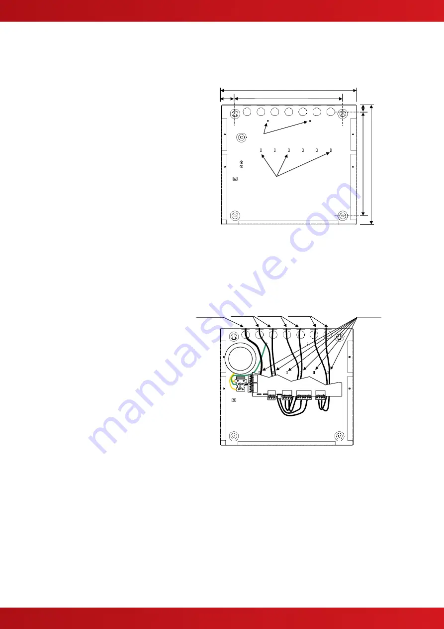
The enclosure is provided with four fixing points.  

The diagram opposite shows the positions of the 
four holes. Use all four positions to ensure the 
panel is held securely to the wall. 

Drill the required holes in the supporting wall using 
a drill bit diameter 7.0 mm and plug with a suitable 
40mm long expansion plug. Affix the panel to the 
wall with M5 screws (length 40mm) or No.10 
screws (length 1½”). 

Ensure that there is sufficient space to allow the 
cover to be removed / replaced when the panel is 
mounted.  

Finally, use a brush to remove any dust or swarf 
from inside the enclosure.  


340 

270 

35 

315


274


17


Cable Tie 
Anchor Points x6 

Earth 
Studs x2 


Enclosure Size and Fixing Point Dimensions 

2.2.4  Remounting the Chassis 

Carefully replace the chassis and fix into place using the two screws. 

Reconnect the chassis earth cable to the spade terminal in the rear of the enclosure and then reconnect the 
supply lead from the transformer to the Base Card.  

2.2.5  Recommended Cable Routing Arrangement 

It is recommended that the routing 
arrangement shown in the diagram 
opposite be employed. 

Segregate the low voltage wiring (Loop 
Circuit, Sounder Circuits and AUX Supply) 
from the AC Mains Wiring. 

Segregate any wiring connected to the 
relay contacts. 

Eyelets are provided in the rear of the back 
box to enable the cables to be securely 
fastened using tie-wraps. 

Refer to Manual 680-014


for further 

information on cable types to be used. 

Refer to specific sections on how to install 
AC Mains input and loop, sounder, relay 
and AUX outputs circuits. 

F
S

2

B
A
T

F
S

1

S
u
p
p
l

y

AC Mains

Relay
Outputs

Sounder
Outputs

Loop
Circuit

Tie-Wrap
Positions


Internal arrangement showing recommended routing of 

cables. 


Содержание MxPro 4 4100S

Страница 1: ...www advancedco com 4100S The operation and functions described in this manual are available from Software Version 4100S 023 013 onwards...

Страница 2: ...evices per Loop Apollo 126 detector call points per loop max Hochiki 127 detector call points per loop max Loop Current 2 max Loop 400mA quiescent 500mA alarm Protocols Apollo S90 XP95 Discovery Explo...

Страница 3: ...egulations 5 2 INSTALLATION 6 2 1 IDENTIFICATION OF PARTS 6 2 2 INSTALLING THE ENCLOSURE 6 2 2 1 Removing and Replacing the Enclosure Cover 6 2 2 2 Removing the Chassis 6 2 2 3 Mounting the Enclosure...

Страница 4: ...TION OBSERVE PRECAUTIONS FOR HANDLING ELECTROSTATIC SENSITIVE DEVICES This equipment is constructed with static sensitive components Observe anti static precautions at all times when handling printed...

Страница 5: ...code of practice or national standard regulations for fire systems installation for example BS5839 1 2002 appropriate to the country and location of the installation 1 1 2 Wiring Regulations The panel...

Страница 6: ...ys ensure that the earth lead spade terminal is securely seated onto the blade terminal in the back box 2 2 2 Removing the Chassis It is recommended that the chassis be removed before fitting the pane...

Страница 7: ...4 17 Cable Tie Anchor Points x6 Earth Studs x2 Enclosure Size and Fixing Point Dimensions 2 2 4 Remounting the Chassis Carefully replace the chassis and fix into place using the two screws Reconnect t...

Страница 8: ...scent Alarm Ahr x 1 256 Battery De rating factor Ahr 3 Use the detector manufacturers technical information to calculate the load on the loop for both the quiescent condition and fire alarm condition...

Страница 9: ...VIEW The View Network option is not available SETUP The network options This Network Node and Next Network Node are not available By default the panel is always Node 0 and the panel cannot be connecte...

Страница 10: ...www advancedco com 10 This page is intentionally left blank...

Страница 11: ...www advancedco com USER NOTES...

Страница 12: ...nced Electronics Ltd Moorland Way Cramlington Northumberland NE23 1WE UK Tel 44 0 1670 707 111 Fax 44 0 1670 707 222 Email sales advancedco com Web www advancedco com Doc Number 680 201 Revision 01B F...

Отзывы: