background image

A - 10

ET600 - 100, 400 - 56091033

8/11

INSTRUCTIONS FOR USE

REVISED DATE

ENGLISH

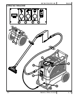
OPERATING THE MACHINE


Follow the instructions in the 

Preparing the Machine for Use

 section of this manual.

2

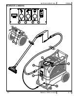
  Turn off all the switches.  Plug the power cords into properly grounded outlets.  Do not connect both cords to the same outlet; the green, 

Circuit Indicator Light 

(E)

 on the switch plate should light up.  If the indicator light does not come on, try different outlets until it does.  Do not 

connect both cords to the same outlet.

3

  Attach the priming hose to the machine and place the open end into the solution tank.

4

  Turn ON the solution pump 

(C)

 and let it run until the pump is fully primed (approximately 30 seconds to 1 minute).  Once the pump is primed, 

turn off the pump and remove the priming hose.  

NOTE:

 If priming is dif

fi

 cult, place the open end of the priming hose into the Vacuum inlet 

hose barb, and turn the vacuum on.  Use your hand to block the open area in the hose barb.  This will allow the pump and the vacuum to work 
together to get the water moving.

Connect a solution line to the Solution Hose Quick Disconnect 

(5)

.  Attach the other end of the solution line to the cleaning tool.

6

  Connect a vacuum hose to the Vacuum Hose Barb 

(2)

.  Attach the other end of the vacuum hose to the cleaning tool.

7

  To use heated water for cleaning, press the Heat Switch 

(D)

 on.  Wait two minutes for the heat exchanger to reach temperature.

Press the Pump Switch 

(C)

 to ON (I).

Press the Vacuum Switch 

(B)

 to ON (I).

10

  Spray through your tool a few times to 

fi

 ll the lines with solution.  Begin cleaning.

11


Note for 400H models only:

 To adjust the solution spray pressure; rotate the Pressure Adjustment Knob 

(13)

 clockwise to increase pressure 

and counterclockwise to decrease pressure.  The pump spraying pressure will be observable at the Pressure Gauge 

(15)

 while spraying.  Make 

sure the cleaning tool is spraying when adjusting the pressure, otherwise the pressure reading will be inaccurate.

12

 Watch 

the 

fl

 uid entering the Recovery Tank Lid 

(1)

.  If there is a large amount of suds in the recovery tank, add a defoamer chemical to the 

recovery tank.

 CAUTION!

• Empty the recovery tank before the 

fl

 uid or foam enters the vacuum motor.

• If foam or liquid escapes from the machine, switch off immediately.


 CAUTION!

Always make sure the 

fl

 oat is clean and travels freely before turning on the machine.  A 

fl

 oat that is stuck will cause the 

vacuum motor to suck in water, resulting in vac motor damage.


13

  The recovery tank has a Recovery Tank Shutoff Float 

(7)

 to block the vacuum system when the recovery tank is full.  You can tell when the 

fl

 oat 

closes by the sudden change in the sound of the vacuum motor.  When the 

fl

 oat closes, the recovery tank must be emptied.  The machine can 

continue to dispense solution, but 

will not

 pick up water with the 

fl

 oat closed.

14

  Monitor the water level in the solution tank. Do not let the pump run dry.  When the solution tank gets low, turn off the pump and the vacuum 

motor, re

fi

 ll the solution tank with water and the proper ratio of cleaning detergent.  Empty the recovery tank and continue cleaning.

15

  When the operator has completed the job; vacuum all unused solution from the solution tank into the recovery tank, turn off the pump, vacuum 

motor and heat exchanger.  Unplug the machine.

16

  Push the machine to a designated waste water “DISPOSAL SITE” and empty the recovery tank.  Drain the recovery tank by opening the drain 

gate 

(3)

 over a drain or a bucket.

17 

Follow the instructions in the 

After Using the Machine

 section of this manual.

Содержание 56105307

Страница 1: ...tructions For Use Original Instructions Instrucciones de uso Mode d emploi Models 56105312 100 56105313 100H 56105314 400H 56105307 400H 8 11 revised 5 14 Form No 56091033 REV B A English B Espa ol C...

Страница 2: ...3 Cautions and Warnings A 4 Grounding Instructions A 5 Know Your Machine A 6 A 7 Know Your Switch Plate A 8 Preparing the Machine for Use A 9 Operating the Machine A 10 A 11 After Use After Using the...

Страница 3: ...Number and Serial Number of your machine for future reference MODEL ________________________________________________ SERIAL NUMBER________________________________________ UNCRATING THE MACHINE When t...

Страница 4: ...the cord Do not handle the plug the cord or the machine with wet hands Extension cords must be 12 3 and no longer than 50 feet Replace the cord or unplug immediately if the ground prong becomes damage...

Страница 5: ...strated in Figures 2 and 3 may be used to connect this plug to a 2 pole receptacle as shown in Figure 2 if a properly grounded outlet is not available The temporary adapter should be used only until a...

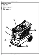
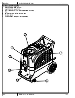
Страница 6: ...11 INSTRUCTIONS FOR USE REVISED DATE ENGLISH KNOW YOUR MACHINE 1 Recovery Tank Lid 2 Vacuum Hose Barb 3 Recovery Tank Drain gate valve 4 Clamp 5 Solution Hose Quick Disconnect 6 Castor 7 Recovery Tank...

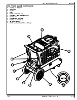
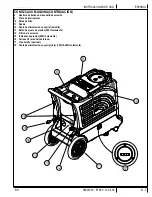
Страница 7: ...Solution Tank Fill Opening 9 Switch Plate 10 Filter Bag 11 Wheel 12 Pigtail Power Cord Yellow 13 Pressure Adjustment Knob 400H only 14 Solution Filter 15 Pressure Gauge 400H only 16 Cord Retainer Str...

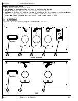
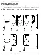
Страница 8: ...d it will turn on the pump D Heat Switch The heat switch will illuminate when it is activated and will turn on the heater NOTE if the green two circuit indicator light is not turned on you may have bo...

Страница 9: ...directions 4 Fill the solution tank 8 with clear water 13 gal 49 L capacity If desired add a detergent or rinse of your choice we recommend a CRI approved detergent If you choose to add a detergent to...

Страница 10: ...tment Knob 13 clockwise to increase pressure and counterclockwise to decrease pressure The pump spraying pressure will be observable at the Pressure Gauge 15 while spraying Make sure the cleaning tool...

Страница 11: ...8 11 A 11 56091033 ET600 100 400 REVISED DATE ENGLISH INSTRUCTIONS FOR USE OPERATING THE MACHINE 15 B C D E 13 7 1 5 2 3...

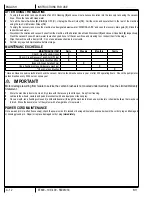
Страница 12: ...MAINTENANCE ITEM Daily Weekly Monthly Yearly Check Clean Tanks Hoses X Check Clean Recovery Tank Shut Off Float X Clean Extraction Wand Tool X Inspect Clean Solution Filter X Use a flushing compound d...

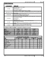
Страница 13: ...15 seconds or about three strokes Heat exchanger needs to be flushed Wrong tool being used Too much water passing through Longer hose or larger diameter hose than standard NO HEAT Heat is not turned o...

Страница 14: ...de conexi n a tierra B 5 Conozca su m quina B 6 B 7 Conozca su placa de interruptores A 8 Preparaci n de la m quina para su utilizaci n B 9 Manejo de la m quina B 10 B 11 Despu s de la utilizaci n De...

Страница 15: ...situado m s adelante para anotar el n mero de modelo y el n mero de serie de la m quina para futuras consultas MODELO_______________________________________________ N MERO DE SERIE____________________...

Страница 16: ...cable ni la m quina con las manos h medas Los alargadores deben ser de 12 3 y su longitud no debe superar los 15 24 m Sustituya el cable o desenchufe inmediatamente si la clavija de tierra est da ada...

Страница 17: ...io tal como se ve en las figuras 2 y 3 en caso de disponerse de un recept culo sin toma a tierra como en la figura 2 Dicho adaptador provisorio se usar solamente hasta que un electricista calificado i...

Страница 18: ...CA SU M QUINA 1 Tapa del dep sito de recuperaci n 2 Leng eta del tubo de aspiraci n 3 Drenaje del dep sito de recuperaci n v lvula de compuerta 4 Pinza 5 Desconexi n r pida del tubo de la soluci n 6 R...

Страница 19: ...Placa de interruptores 10 Bolsa de filtro 11 Rueda 12 Cable de alimentaci n en espiral amarillo 13 Bot n de ajuste de presi n 400H solamente 14 Filtro de la soluci n 15 Indicador de presi n 400H sola...

Страница 20: ...a El interruptor de la bomba se iluminar cuando est activado y encender la bomba D Interruptor de calor El interruptor de calor se iluminar cuando est activado y encender el calefactor NOTA Si la luz...

Страница 21: ...aci n de acuerdo con las recomendaciones del fabricante 4 Llene el dep sito de soluci n 8 con agua limpia capacidad de 13 gal 49 L Si lo desea a ada un detergente recomendamos un detergente aprobado p...

Страница 22: ...as agujas del reloj para aumentar la presi n y en el sentido contrario a las agujas del reloj para disminuir la presi n La presi n de pulverizaci n de la bomba se podr observar en el man metro 15 dura...

Страница 23: ...8 11 B 11 56091033 ET600 100 400 REVISED DATE ESPA OL INSTRUCCIONES DE USO MANEJO DE LA M QUINA 15 B C D E 13 7 1 5 2 3...

Страница 24: ...dep sitos y tubos Limpiar e inspeccionar el flotador de cierre del dep sito de recuperaci n Limpiar la varilla herramienta de extracci n Limpiar e inspeccionar el filtro de la soluci n Utilice un com...

Страница 25: ...iraci n POCO CALOR Pulverizaci n demasiado prolongada Intente pulverizar durante 12 15 segundos o unos tres golpes Es necesario limpiar el intercambiador de calor Se est utilizando una herramienta equ...

Страница 26: ...it C 4 Instructions de mise la terre C 5 Apprenez conna tre votre machine C 6 C 7 Apprenez conna tre votre plaque d interrupteurs C 8 Pr paration de la machine C 9 Fonctionnement de la machine C 10 C...

Страница 27: ...ue d une utilisation ult rieure MODELE _______________________________________________ NUMERO DE SERIE______________________________________ DEBALLAGE DE LA MACHINE Lors de la livraison de la machine...

Страница 28: ...ff e Pour d brancher la machine saisissez la prise et non le cordon Ne manipulez pas la prise le cordon ou la machine avec les mains humides La longueur des rallonges doit tre de 1 15 m maximum Rempla...

Страница 29: ...croquis 2 si une prise avec mise la terre n est pas disponible L adaptateur temporaire devrait etre utilis seulement jusqu ce qu une prise avec mise la terre soit install e par un lectricien qualifi L...

Страница 30: ...TRE VOTRE MACHINE 1 Couvercle du r servoir de r cup ration 2 Raccord filet du tuyau d aspiration 3 Vidange du r servoir de r cup ration robinet vanne 4 Verrou 5 Raccord rapide du tuyau de solution 6 R...

Страница 31: ...rvoir de solution 9 Plaque d interrupteurs 10 Sac filtre 11 Roue 12 Cordon lectrique jaune 13 Bouton de r glage de la pression 400H uniquement 14 Filtre de solution 15 Manom tre 400H uniquement 16 Att...

Страница 32: ...t en marche la pompe D Interrupteur de chauffage L interrupteur de chauffage s claire quand il est activ et il met en marche le syst me de chauffage NOTE si le voyant vert des deux circuits n est pas...

Страница 33: ...solution 8 d eau propre capacit de 49 litres Si vous le souhaitez ajoutez un d tergent ou un m lange de nettoyage de votre choix nous recommandons un d tergent approuv CRI Si vous ajoutez un d tergent...

Страница 34: ...r diminuer la pression La pression de pulv risation de la pompe peut tre v rifi e pendant la pulv risation gr ce au manom tre 15 Assurez vous que l accessoire de nettoyage vaporise pendant que vous aj...

Страница 35: ...8 11 C 11 56091033 ET600 100 400 REVISED DATE FRAN AIS MODE D EMPLOI UTILISATION DE LA MACHINE 15 B C D E 13 7 1 5 2 3...

Страница 36: ...cation nettoyage du syst me de fermeture flotteur du r servoir de r cup ration X Nettoyage de l accessoire lance d extraction X Inspection et nettoyage du filtre de solution X Utilisez un compos de ri...

Страница 37: ...ation trop longue Tentez de vaporiser pendant 12 15 secondes ou environ trois appuis L changeur de chaleur doit tre nettoy Mauvais accessoire utilis Circulation d une quantit d eau excessive Tuyau plu...

Страница 38: ......

Страница 39: ......

Страница 40: ...800 989 6566 2014 Nilfisk Advance Inc A Nilfisk Advance Brand Nilfisk Advance Equipamentos de Limpeza Ltda Av Dep Em lio Carlos 2 499 Bairro do Lim o 02721 200 S o Paulo SP Brasil www nilfisk advance...

Отзывы: