Chapter 3. Operation
40
TSU 600 User Manual
61200.076L2-1
OK
• 1
MODULE
TEST
TSU 600
ALARM
OK
• 2
TEST
ALARM
OK
• 3
TEST
ALARM
ALARM
ERROR
TEST
COPY
HOME
SHIFT
OK
REMOTE
A
B
C
REMOTE
ALARM
CLEAR
D
E
F
0
#
1
2
3
7
8
9
4
5
6
CANCEL
ENTER
OK
• 5
TEST
ALARM
OK
• 4
TEST
ALARM
OK
• 6
TEST
ALARM
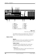
1. REMOTE
2. LCD Window
3. CSU Status
4. Key Pad
5. Module Status
6. CANCEL
7. Up and Down Arrow Keys
9
11
13
1
3
2
7
10
12 14
6
8
4
5
8. ENTER
9. COPY
10. REMOTE
11. HOME
12. ALARM
13. SHIFT
14. CLEAR
Figure 3-1
TSU 600 Front Panel Layout
The display panels and operation keys called out in
Figure 3-1 are described in the following sections:
Display Panels
Remote
When illuminated, this panel indicates that the TSU
600
is accessed remotely by the PC program.
Module Status
The module status LEDs display the operational
condition of ports installed in the option slots.
•
OK
(green)
Indicates the operation is in the normal mode and
no errors have been detected.
Содержание TSU 600
Страница 1: ...61200 076L2 1B July 1997 TSU 600 USER MANUAL Part Number 1200076L2 1200076L2 DC...
Страница 4: ...Table of Contents...
Страница 96: ...Chapter 3 Operation 84 TSU 600 User Manual 61200 076L2 1...
Страница 103: ...Chapter 4 Example Operations 61200 076L2 1 TSU 600 User Manual 91 Figure 4 4 First Two Network NI Menu Items...
Страница 118: ...Chapter 4 Example Operations 106 TSU 600 User Manual 61200 076L2 1...
Страница 126: ...Appendix C System Configuration Charts 114 TSU 600 User Manual 61200 076L2 1...
Страница 128: ...Appendix D TSU 600 System Messages 116 TSU 600 User Manual 61200 076L1 1...


