background image

Section 5 DLP-2 

Total Access 850 System Manual

 218

© 2004 ADTRAN, Inc.

64203376L1-1B

1.

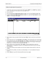
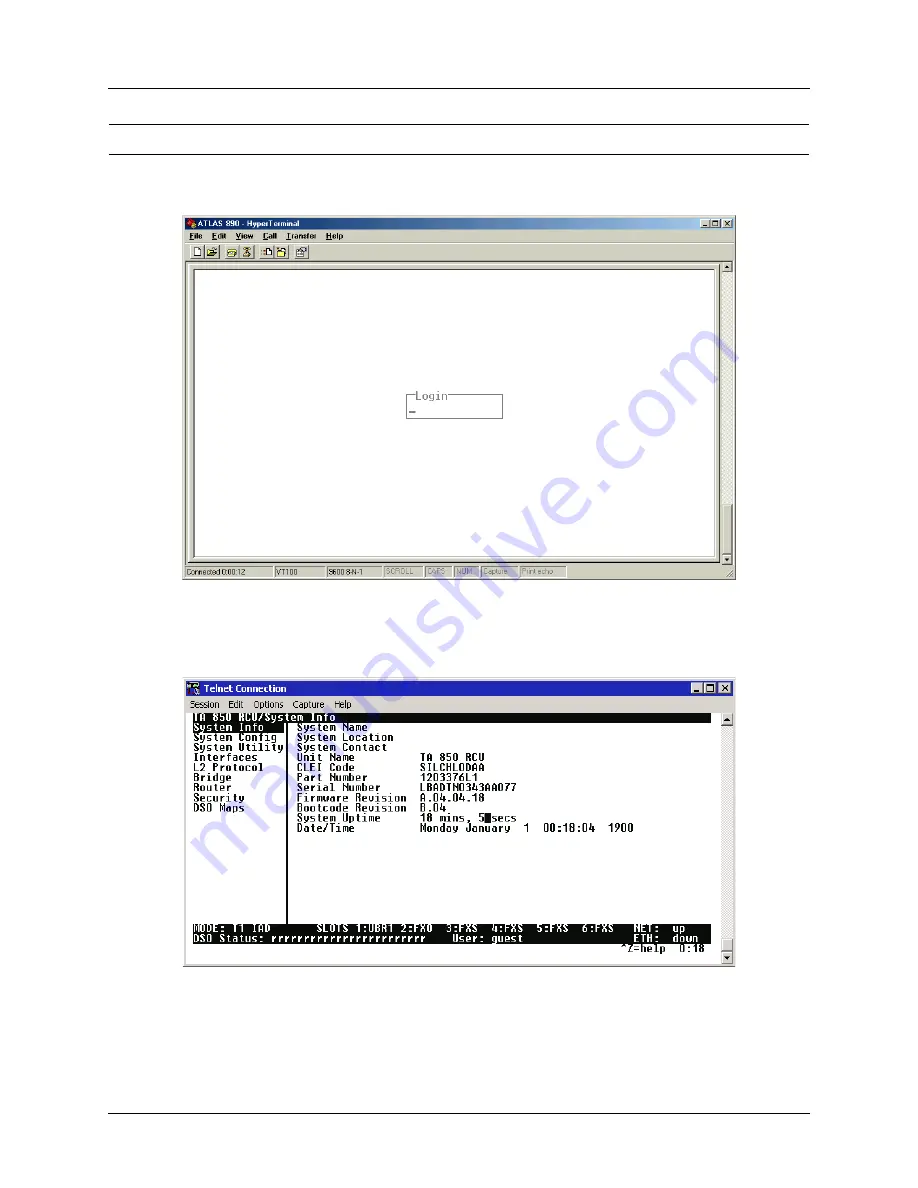
After connecting to the system, press any key to display the Login screen shown here. The blinking 
cursor at the Login field indicates that a password must be entered.

2.

Enter the password for the Total Access 850 at the Login field. There is no manufacturer’s default 
password; press 

<Enter>

 to enter the Total Access 850 menus.

3.

Upon entering the correct password, the Total Access 850 main menu is displayed as shown below.

4.

You are now logged in to the Total Access 850 menu system.

Perform the steps below in the order listed.

Содержание Total Access 850

Страница 1: ...Unit BCU 1200373L2 T1 BCU with DSX Port 4203376L1 TDM T1 Router Control Unit RCU with TDM Software 4203376L1 ATM T1 RCU with ATM Software 1203376L1 3rd Generation T1 RCU 1200377L1 SDSL RCU 1200377L2 2nd Generation SDSL RCU 1203384L2 Echo Canceller with ADPCM 1175006L2 Power Supply Unit 1175043L3 AC Supply Battery Charger ...

Страница 2: ...cial incidental or consequential damages or for commercial losses even if ADTRAN has been advised thereof as a result of issue of this publication About this Manual This manual provides a complete description of the Total Access 850 system and system software The purpose of this manual is to provide the technician system administrator and manager with general and specific information related to th...

Страница 3: ... this manual The previous version of this product was covered under document 64200376L1 1 B August 2004 Update licensing and warranty agreement correct third generation part numbers Notes provide additional useful information Cautions signify information that could prevent service interruption Warnings provide information that could prevent damage to the equipment or endangerment to human life ...

Страница 4: ... bowl kitchen sink laundry tub in a wet basement or near a swimming pool 2 Avoid using a telephone other than a cordless type during an electrical storm There is a remote risk of shock from lightning 3 Do not use the telephone to report a gas leak in the vicinity of the leak 4 Use only the power cord power supply and or batteries indicated in the manual Do not dispose of batteries in a fire They m...

Страница 5: ... This unit contains no user serviceable parts 6 An FCC compliant telephone cord with a modular plug is provided with this equipment This equipment is designed to be connected to the telephone network or premises wiring using an FCC compatible modular jack which is compliant with Part 68 and requirements adopted by ACTA 7 The following information may be required when applying to your local telepho...

Страница 6: ... environment This equipment generates uses and can radiate radio frequency energy and if not installed and used in accordance with the instruction manual may cause harmful interference to radio frequencies Operation of this equipment in a residential area is likely to cause harmful interference in which case the user will be required to correct the interference at his own expense Shielded cables m...

Страница 7: ...ed for eventual conversion into voice band analog signal and transmitted on the network The affidavit shall affirm that either no encoded analog content or billing information is being transmitted or that the output of the device meets Part 68 encoded analog content or billing protection specifications End user customer will be responsible to file an affidavit with the local exchange carrier when ...

Страница 8: ... content and billing protection is factory set and is not under the control of the customer I attest that the operator s maintainer s of the digital CPE responsible for the establishment maintenance and adjustment of the encoded analog content and billing information has have been trained to perform these functions by successfully having completed one of the following check appropriate blocks A A ...

Страница 9: ...the percentage of the total load to be connected to a telephone loop which is used by the device to prevent overloading The termination on a loop may consist of any combination of devices subject only to the equipment that the total of the LNs of all devices does not exceed 100 The ringer equivalence number REN assigned to each terminal adapter is used to determine the total number of devices that...

Страница 10: ...ion and Training ADTRAN will replace or repair this product within the warranty period if it does not meet its published specifications or fails while in service Warranty information can be found at www adtran com warranty A return material authorization RMA is required prior to returning equipment to ADTRAN For service RMA requests training or more information use the contact information given be...

Страница 11: ...Customer Service Product Support Information and Training 64203376L1 1B 2004 ADTRAN Inc 11 When needed further pre sales assistance is available by calling our Applications Engineering Department Applications Engineering 800 615 1176 ...

Страница 12: ...xtended Services ACES program offers multiple types and levels of installation and maintenance services which allow you to choose the kind of assistance you need This support is available at For questions call the ACES Help Desk Training The Enterprise Network EN Technical Training Department offers training on our most popular products These courses include overviews on product features and funct...

Страница 13: ...a VT100 Terminal or PC to the CRAFT Port 215 DLP 2 Logging in to the System 217 DLP 3 Setting IP Parameters for the Total Access 850 219 DLP 4 Verifying Communications Over an IP LAN 221 DLP 5 Connecting to the Total Access 850 Using Telnet 225 DLP 6 Adding Removing Users and Changing Password Security Levels 229 DLP 7 Updating the Firmware using TFTP 233 DLP 8 Updating the Firmware using XMODEM 2...

Страница 14: ...Table of Contents Total Access 850 System Manual 14 2004 ADTRAN Inc 64203376L1 1B ...

Страница 15: ...21 BCU with Fractional T1 P N 1200373L2 21 T1 RCU P N 4203376L1 TDM 4203376L1 ATM and 1203376L1 21 SDSL RCU P N 1200377L1 1200377L2 21 Power Supply Unit P N 1175006L2 22 Echo Canceller with ADPCM P N 1203384L2 22 Nx56 64K V 35 Module P N 1200372L1 22 Quad FXS Access Module P N 1175408L2 22 Quad FXO Access Module P N 1175407L2 22 OCU DP Access Module P N 1180005L1 23 U BR1TE Access Module P N 11800...

Страница 16: ...Section 1 System Description Total Access 850 System Manual 16 2004 ADTRAN Inc 64203376L1 1B ...

Страница 17: ... features functions and access ports on and off Easy access to modules common modules power supplies and the battery back up system simplifies maintenance procedures Hot swappable modules may be replaced without disrupting other units The four circuit per module design ensures that only four analog circuits are affected when replacing a module The Total Access 850 is a compact NEBS compliant cabin...

Страница 18: ...different system modules including the power supply system resource modules and access modules System Modules Bank Controller Unit BCU P N 1200373L1 BCU with Fractional T1 P N 1200373L2 T1 Router Control Unit RCU with TDM software P N 4203376L1 TDM T1 Router Control Unit RCU with ATM software P N 4203376L1 ATM 3rd Generation T1 Router Control Unit RCU P N 1203376L1 SDSL RCU P N 1200377L1 2nd Gener...

Страница 19: ... provides the network interface for the Total Access 850 system The RCU can provision test and provide status for any card in the system A faceplate DB 9 CRAFT interface provides access for a VT100 terminal for screen menu provisioning and bantam test jacks provide transmit and receive monitoring capabilities Terminal menu access is also provided through the RJ 45 CRAFT interface located on the re...

Страница 20: ...source slots A and B Nx56 64K V 35 Module P N 1200372L1 This module is only available in Total Access 850 systems using a BCU The Nx56 64k V 35 Module activates the V 35 port on the rear of the chassis This is a dual slot module and must be installed in the system resource slots A and B Quad FXS Access Module P N 1175408L2 The Quad FXS Module provides analog voice extension for the Total Access 85...

Страница 21: ...The Dual V 35 Access Module is a DSU data port with two circuits that each deliver serial data over a V 35 interface The module is designed as a dual slot module it requires two slots in the Total Access 850 chassis Each circuit of the Dual V 35 Access Module provides up to 24 channels of data in 56 or 64 kbps increments Design operation is to transmit or receive high rate synchronous data from da...

Страница 22: ...Section 1 System Description Total Access 850 System Manual 22 2004 ADTRAN Inc 64203376L1 1B ...

Страница 23: ... Wire Wrap Connection P3 39 Power Connections P6 and P7 39 Access Module Interfaces 40 Power Supply Unit P N 1175006L2 40 Quad FXS Access Module P N 1175408L2 41 Quad FXO Access Module P N 1175407L1 43 UBR1TE Access Module P N 1180020L1 45 OCU DP Access Module P N 1180005L1 49 E M TO Access Module P N 1180402L1 49 Dual V 35 Access Module P N 1180025L1 50 DSX 1 Access Module P N 1200385L1 52 FIGURE...

Страница 24: ...or Pinout 39 Table 19 PSU Faceplate LEDs 41 Table 20 Quad FXS Module Faceplate LEDs 41 Table 21 Quad FXS Module Specifications 42 Table 22 Quad FXS Module Compliance Codes 43 Table 23 Quad FXO Module Faceplate LEDs 43 Table 24 Quad FXO Module Specifications 44 Table 25 Quad FXO Module Compliance Codes 45 Table 26 UBR1TE Module Faceplate LEDs 45 Table 27 UBR1TE Slot Amphenol Assignment 46 Table 28 ...

Страница 25: ...Regardless of the configuration of access modules installed in the chassis the following power requirements apply AC System 90 130 VAC 60 Hz 50 Watt Max DC System 40 56 VDC 50 Watt Max 3 REVIEWING THE FRONT PANEL DESIGN Figure 1 shows the Total Access 850 front panel Refer to Access Module Interfaces on page 40 for a discussion of available modules and the front panel functions of each Figure 1 To...

Страница 26: ... the chassis Once the BCU is installed any software provisioning made will override the DIP switch settings If the BCU is withdrawn and reinserted power cycled the software options remain in effect If a DIP switch setting is changed while the BCU is withdrawn the new DIP switch setting takes effect If none of the DIP switch settings were changed the unit will be provisioned for the last software s...

Страница 27: ... sent from a remote network device or test equipment ON Disabled OFF Enabled S1 5 S1 6 Timing Mode A Timing Mode B Determines the clock source options for the Total Access 850 system S1 5 S1 6 Function OFF OFF Loop timing Derives timing from the network T1 ON OFF External Timing Derives timing from the external bits clock OFF ON Local Timing Clock generated from internal timing source ON ON Loop T...

Страница 28: ...nt is used to test DS0 access modules such as the OCU DP DS0 DP or UBR1TE Once the test equipment is connected to the reference clock source individual tests can be performed on DS0 access modules using the faceplate bantam jacks on each unit Figure 3 on page 28 illustrates the DB 9 TEST connector Figure 3 BCU DB 9 Test Connector T1 Router Controller Unit 4200376L1 TDM and 4200376L1 ATM The follow...

Страница 29: ... RD Receive Data Output 3 TD Transmit Data Input 5 SG Signal Ground Table 4 T1 RCU Faceplate LEDs For these LEDs This color light Indicates that PWR OFF there is no power to the system Solid GREEN the system is connected to an active power source T1 ALARM OFF there are no active T1 alarms on the system ON there is an active T1 alarm yellow red or blue alarm on the system T1 TEST AMBER the network ...

Страница 30: ...ys the CRAFT port pinout Faceplate LEDs The faceplate LEDs provide status information using a color coded message format Table 6 gives a description of all faceplate LEDs for the T1 RCU when used with the Total Access 850 system Table 5 3rd GEN T1 RCU CRAFT DB 9 Female Pinout Pin Name Description 1 4 6 9 UNUSED 2 RD Receive Data Output 3 TD Transmit Data Input 5 SG Signal Ground Clock and Data Rec...

Страница 31: ... color light Indicates that T1 GREEN the network T1 interface is operational RED the network T1 is in Red Alarm meaning the T1 is down not connected or framing is improperly configured AMBER the network T1 is in test mode loopback ETH GREEN there is a valid 10 Mbps Ethernet link AMBER there is a valid 100 Mbps Ethernet link RED there is no active Ethernet link Clock and Data Recovery MON IN Test J...

Страница 32: ...a Output 3 TD Transmit Data Input 5 SG Signal Ground Table 8 SDSL RCU Faceplate LEDs For these LEDs This color light Indicates that PWR OFF there is no power to the system Solid GREEN the system is connected to an active power source DATA Blinking GREEN there is transmit data detected on the network interface NET ALRM OFF there are no active network alarms on the system ON there is an active netwo...

Страница 33: ...lications will not require removal of the rear cover Figure 6 shows the Total Access 850 backplane and Table 10 on page 34 gives the backplane connections Figure 6 Total Access 850 Rear Panel Table 9 SDSL RCU DIP Switch S1 Options Switch Function Description S1 1 Firmware Mode ON down The unit powers up in the firmware update mode This mode is not used for normal operation OFF Disables the firmwar...

Страница 34: ...e P5 wire wrap strip alarms P6 4 pin jack primary 48 V in P7 3 lug terminal alternate 48 V in JP1 RJ 48 E NET 10BaseT Ethernet JP2 RJ 48 T1 primary T1 interface JP3 RJ 48 FT1 DSX1 interface JP4 RJ 48 MAINT EIA 232 CRAFT interface J1 V 35 Nx56K 64K Only the 3rd Generation RCUs provide a 10 100BaseT connection All other available RCU Ethernet interfaces are 10BaseT The 10 100BaseT Ethernet LAN inter...

Страница 35: ...inout DSX 1 Connection JP3 The Total Access 850 system provides a single DSX 1 port located in the rear of the unit The DSX 1 interface provides the following functions AMI or B8ZS Manual line build out D4 or ESF framing The Total Access 850 provides dual T1 connection points In all cases only one of the connection points is used When wire wrapping of the T1 is utilized using P3 a blank plug must ...

Страница 36: ...0 or PC control Acts as an interface for flash memory software downloads using XMODEM Table 14 shows the rear CRAFT port pinout Pin Name Description 1 R TXDATA RING Transmit data from the network 2 T TXDATA TIP Transmit data from the network 3 UNUSED 4 R1 RXDATA RING Receive data toward the network 5 T1 RXDATA TIP Receive data toward the network 6 7 8 UNUSED Table 14 Rear CRAFT Pinout Pin Name Des...

Страница 37: ... the PSU faceplate If the 3 Amp power fuse on the PSU trips the 48ALM relay will close providing a 48 VDC signal on that pin This alarm cannot be overridden by the ACO pushbutton Refer to Table 17 for alarm notifications Table 16 shows the pinout for the Alarm Relay connector Pin CCIT Description Pin CCIT Description A 101 Protective ground PG V 115 RX clock RC A to DTE B 102 Signal ground SG X 11...

Страница 38: ... Figure 7 details the connector pinout Figure 7 Connector Pinout Alarm Condition Relays Activated MJR MJVR 48 ALM Red Alarm X X Yellow Alarm X X AIS Alarm X X PSU Power Fuse Fails X X X Alarms ACO Deactivates X X Note ACO will not deactivate MJR after a power fuse failure 26 1 27 2 28 3 29 4 30 5 31 6 32 7 33 8 34 9 35 10 36 11 37 12 38 13 39 14 40 15 41 16 42 17 43 18 44 19 45 20 46 21 47 22 48 2...

Страница 39: ... connection is the modular plug which receives 48 VDC from an approved ADTRAN power supply battery charging unit for example P N 1175043L2 The alternate connection is screw terminal P7 which can be used if 48 VDC is available as in central office applications The screw terminal connection is shown in Figure 8 on page 40 Network T1 connections can have up to 140 VDC Use caution when making T1 conne...

Страница 40: ...ower Through switchmode operation the PSU converts the incoming 48 VDC to regulated 5 VDC 3 3 VDC 7 5 VDC 26 VDC and 48 VDC for distribution to other modules Ring voltage circuitry within the PSU generates 105 Vrms 20 Hz ring voltage for distribution to the system s FXS cards Ring voltage is disabled by pushing the RING ENABLE button Faceplate LEDs The faceplate LEDs provide status information usi...

Страница 41: ... Indicates that POWER OFF the system is disconnected from the power source or powered off GREEN the system is connected to a power source and is powered on RING OFF ring generation is disabled for the system GREEN ring generation is enabled for the system BANK ALM OFF the system is in normal operation Solid RED there is currently an active alarm condition Blinking RED there was an alarm condition ...

Страница 42: ...ERL 28 dB SRL 20 dB Trans Hybrid Loss 900 Ω 2 16 µF ERL 28 dB SRL 20 dB Longitudinal Balance 200 500 and 1000 Hz 58 dB min 63 dB avg 3000 Hz 53 dB min 58 dB avg Frequency Response 300 to 3400 Hz 0 5 dB and 1 0 dB Idle Channel Noise 20 dBrnC 26 1 27 2 28 3 29 4 30 5 31 6 32 7 33 8 34 9 35 10 36 11 37 12 38 13 39 14 40 15 41 16 42 17 43 18 44 19 45 20 46 21 47 22 48 23 49 24 50 25 R T R T R T R T R ...

Страница 43: ...with the Total Access 850 system Signal to Distortion Ratio 0 to 30 dBm0 33 dB 30 to 40 dBm0 27 dB 40 to 45 dBm0 22 dB Relative Humidity Up to 95 noncondensing Temperature Operate at 40 C to 65 C Store at 40 C to 70 C Tests Self test digital loopback network on hook off hook customer ring and 1000 Hz 1 kHz tone generation Table 22 Quad FXS Module Compliance Codes CODE IN OUT Power Code PC C C Tele...

Страница 44: ...Idle Channel Noise 20 dBrnC Signal to Distortion Ratio 0 to 30 dBm0 33 dB 30 to 40 dBm0 27 dB 40 to 45 dBm0 22 dB Relative Humidity Up to 95 noncondensing Temperature Operate at 40 C to 65 C Store at 40 C to 70 C Tests Self test digital loopback network on hook off hook customer ring and 100 Hz tone generation 26 1 27 2 28 3 29 4 30 5 31 6 32 7 33 8 34 9 35 10 36 11 37 12 38 13 39 14 40 15 41 16 4...

Страница 45: ...these LEDs This color light Indicates that STATUS OFF both the loop and the carrier synchronization are established Solid RED neither the loop nor the carrier synchronization is established Blinking RED every two seconds loop synchronization is established but carrier synchronization is not Blinking RED twice every second carrier synchronization is established but loop synchronization is not GREEN...

Страница 46: ...creen menus accessed via the faceplate CRAFT interface port Table 28 provides the DIP switch setting details Table 27 UBR1TE Slot Amphenol Assignment Total Access 850 Slot Port 1 T R 1 26 1 2 30 5 3 34 9 4 38 13 5 42 17 6 46 21 Table 28 BCU DIP Switch S1 Options Switch Function Description S1 1 MODE Sets the termination mode as LULT RT Typical or LUNT COT Typical ON Unit is installed as Adjacent t...

Страница 47: ...is not provided LUNT Mode indicates a Tandem Office Sink configuration and wake up tones are provided S1 3 S1 4 S1 5 Service for S1 3 B1 S1 4 B2 S1 5 D Selects the service level to option the U BR1TE module to deliver full ISDN 2B D or any of the following levels Service Level S1 3 S1 4 S1 5 2B D 2B B1 D B2 D B1 B2 D ON ON ON ON ON OFF ON OFF ON OFF ON ON ON OFF OFF OFF ON OFF OFF OFF ON S1 6 Zero...

Страница 48: ...ata Rate 160 kbps total 144 kbps available to customer Signal Format 2B1Q Transmit Power 13 dBm to 14 dBm nominal DS1 Facility Interface BR1 10 compatible equipment Network Compatibility Interface ISDN and other digital service according to TR NWT 000397 Mechanical Dimensions 3 125 H x 0 62 W 1 01 D Weight 1 lb Power Current Draw 0 023 A maximum 48V Environmental Temperature Operating 40 C to 70 C...

Страница 49: ...premises or tandem central office applications The E M TO module supports both 2 and 4 wire operation This module is currently only supported by BCU L1 and L2 Table 32 gives the E M TO module pinout The OCU DP Access Module may be used for intra building networks only This interface should not be connected to public networks Table 31 OCU DP Pinout Total Access 850 Slot T R RX T1 R1 TX 1 26 1 27 2 ...

Страница 50: ...LEDs for the Dual V 35 Module when used with the Total Access 850 system Interface Pinouts Table 34 provides the interface pinout for the DB 26 and V 35 interfaces Table 33 Dual V 35 Module Faceplate LEDs For these LEDs This color light Indicates that Status GREEN the module is operating normally RED there is a card failure or the T1 is down or there is no valid data transfer occurring AMBER there...

Страница 51: ... B to DTE 24 V RX clock RC A to DTE 25 X RX clock RC B to DTE 26 W External TX clock ETC B from DTE Table 35 Dual V 35 Module Specifications Data Rates 56 kbps to 1 536 Mbps per interface Relative Humidity Up to 95 noncondensing Cable Assembly DB 26 to V 35 P N 1200167L1 Temperature Operate at 40 C to 65 C Store at 40 C to 85 C Tests Self test DTE loopback Network Loopback 511 Pattern generation E...

Страница 52: ...ported by the T1 RCU only Faceplate LEDs The faceplate LEDs provide status information using a color coded message format Table 37 on page 53 gives a description of all faceplate LEDs for the DSX 1 Module when used with the Total Access 850 system Table 36 Dual V 35 Module Compliance Codes CODE IN OUT Power Code PC C C Telecommunication Code TC Installation Code A The DSX 1 interface provided on t...

Страница 53: ...ogress Blinking AMBER the card is initializing during startup Table 38 DSX 1 Module Interface Pinout Pin Name Description 1 R1 RXDATA RING Receive data from the network RING 2 T1 RXDATA TIP Receive data from the network TIP 3 UNUSED 4 R TXDATA RING Transmit data towards the network RING 5 T TXDATA TIP Transmit data towards the network TIP 6 7 8 UNUSED Table 39 DSX 1 Module Specifications Capacity ...

Страница 54: ...Section 2 Engineering Guidelines Total Access 850 System Manual 54 2004 ADTRAN Inc 64203376L1 1B ...

Страница 55: ...ions 60 Required Clearances 60 Wallmounting the Chassis 60 Installing Modules 61 Instructions for Installing the Power Supply Unit P N 1175006L2 61 Instructions for Installing the Total Access 850 Controller and Access Modules 62 Module Shipping Contents 62 Quad FXO Access Module P N 1175407L2 62 Quad FXS Access Module P N 1175408L2 62 UBR1TE Access Module P N 1180020L1 62 OCU DP Access Module P N...

Страница 56: ...deep penetration into the carton with sharp objects After unpacking the unit inspect it for possible shipping damage If the equipment has been damaged in transit immediately file a claim with the carrier and then contact ADTRAN Customer Service see Customer Service Product Support Information and Training in the front of this manual To prevent electrical shock do not install equipment in a wet loc...

Страница 57: ...ical Business Equipment of July 28 1995 An equipment grounding conductor that is not smaller in size than the ungrounded branch circuit supply conductors is to be installed as part of the circuit that supplies the product or system Bare covered or insulated grounding conductors are acceptable Individually covered or insulated equipment grounding conductors shall have a continuous outer finish that...

Страница 58: ...lled using the appropriate crimping tool AMP P N 59250 T EAD Crimping Tool or equivalent 6 SUPPLYING POWER TO THE UNIT On the Total Access 850 chassis the incoming power termination point is on either of two backplane connections P6 or P7 see Power Connections P6 and P7 on page 39 Both sources connect directly to the PSU Connector P6 is used when the chassis is powered by an approved ADTRAN AC DC ...

Страница 59: ...to be used make those terminal connections last 5 Carefully route wiring through the exit port 6 Position and align the access cover tabs to the slots insert the tabs and slide the cover up slightly until the screw holes are aligned Ensure that exit wiring is not pinched or damaged 7 Reinsert the hold down screw This unit shall be installed in accordance with Article 400 and 364 8 of the NEC NFPA ...

Страница 60: ...d connects with standard fasteners and hand tools Four 8 x 3 4 inch pan head wood screws Drill and drill bit set Flat head screwdriver medium Two Phillips head screwdrivers small medium Wire wrap gun optional 25 pair male amphenol cable customer connection Selected punch down block and tool Installing the Chassis 1 Position the chassis at the desired location observe required clearances and ensure...

Страница 61: ...mon card area in the position labeled PSU The unit is mechanically keyed to prevent insertion in any other slot 2 To install the PSU grasp the unit by the faceplate while supporting the bottom side Access modules are intended to be serviced by qualified service personnel only Electronic modules can be damaged by static electrical discharge Before handling modules put on an antistatic discharge wri...

Страница 62: ...ss module by the faceplate while supporting the bottom side 2 Align the module edges to the guide grooves for the designated slot 3 Insert the module until the edge connector seats firmly into the backplane 4 Lock the module in place by pushing in on the locking lever 5 Connect the cables to the associated device s All wiring connections terminate on the backplane of the chassis 9 MODULE SHIPPING ...

Страница 63: ...id E M TO Access Module P N 1180402L1 Shipping Contents The ADTRAN shipment of the E M TO Access Module includes the following items E M TO Access Module E M TO Access Module Job Aid Dual V 35 Access Module P N 1180025L1 Shipping Contents The ADTRAN shipment of the Dual V 35 Access Module includes the following items Dual V 35 Access Module Dual V 35 Access Module Job Aid DSX 1 Module P N 1200385L...

Страница 64: ...Section 3 Network Turnup Procedure Total Access 850 System Manual 64 2004 ADTRAN Inc 64203376L1 1B ...

Страница 65: ...em Info 75 System Config 77 System Utility 90 Interfaces 96 Interfaces Network T1 96 Interfaces DSX 100 Interfaces ETH 103 Interfaces V35 104 Interfaces FXS 105 Interfaces FXO 109 Interfaces DSX 1 Module 111 Interfaces UBR1TE Module 113 L2 Protocol T1 TDM Firmware 118 L2 Protocol T1 TDM Firmware T1 Interface 119 L2 Protocol T1 TDM Firmware T1 Interface PPP 120 L2 Protocol T1 TDM Firmware T1 Interf...

Страница 66: ...ility Menu 90 Figure 6 Interfaces Menus 96 Figure 7 UBR1TE Network Configurations 114 Figure 8 L2 Protocol T1 TDM Menu 118 Figure 9 L2 Protocol T1 TDM Menu 130 Figure 10 Bridge Menu 147 Figure 11 Router Menu 150 Figure 12 Security Menu 173 Figure 13 DS0 Maps Menu 181 Figure 7 Application Diagram 201 Figure 10 Application Diagram 206 TABLES Table 1 Password Security Level 74 Table 2 Instructions fo...

Страница 67: ... of the Total Access 850 Figure 1 Top Level Terminal Menu Window Menu Path The first line of the terminal menu window the menu path shows the session s current position path in the menu structure For example Figure 1 shows the top level menu with the cursor on the SYSTEM CONFIG submenu therefore the menu path reads TOTAL ACCESS 850 SYSTEM CONFIG Window Panes When you first start a terminal menu se...

Страница 68: ...ternate view Fields and submenu names may vary slightly in this view Figure 2 Alternate Menu View Window Pane Navigation Use the following chart to assist you in moving between and within the two window panes To do this Press this key Move from left pane to right pane Tab Enter Right arrow Move from right pane to left pane Tab Escape Left arrow Backspace Move within each pane Up arrow Down arrow L...

Страница 69: ... interface located on the rear of the chassis This information is only available when using a 3rd Generation RCU Extended Help displays information about selected commands CTRL A Navigation Help lists characters used for navigating the terminal menu and session management CTRL Z System Time displays the current time Network Status displays network status information as UP or DOWN Navigating using ...

Страница 70: ...reconnecting the terminal session CTRL R To do this Press this key Restore factory default settings This setting restores the factory defaults based on the location of the cursor If the cursor is on an interface line in the INTERFACES menu then only the selected interface is updated to factory defaults F Copy selected items to the clipboard The amount of information you can copy depends on the cur...

Страница 71: ...elp select the appropriate menu Increment the value of certain types of fields by one when you paste information into those fields Decrement the value of certain types of fields by one when you paste information into those fields Save the current configuration immediately to RAM CTRL W Insert a new list item For example add a new item to the TELNET USER connection list by pressing I while the curs...

Страница 72: ...ssword security levels only apply to Telnet connections Connecting to the system through the RCU faceplate CRAFT or rear CRAFT interface automatically provides maximum rights Table 1 Password Security Level Security Level Description Full Permission to edit every menu item including creating and editing passwords maximum rights Support Access to all commands except passwords Config Access to all c...

Страница 73: ...ield including spaces and special characters such as an underscore This name will appear on the top line of all screens SYSTEM INFO SYSTEM LOCATION Provides a user configurable text string for the location of the unit This field is to help you keep track of the actual physical location of the unit You can enter up to 127 alphanumeric characters in this field including spaces and special characters...

Страница 74: ...only Displays the current firmware revision level of the unit SYSTEM INFO BOOTCODE REVISION Read only Displays the current bootcode revision SYSTEM INFO SYSTEM UPTIME Displays the length of time the Total Access 850 system has been running Each time you reset the system this value resets to 0 days 0 hours 0 min and 0 secs SYSTEM INFO DATE TIME Displays the current date and time including seconds T...

Страница 75: ...nector located on the rear of the unit or via the DB 9 connector on the front of the unit SYSTEM CONFIG MANAGEMENT CRAFT PORT PASSWORD PROTECT When PASSWORD PROTECT is set to NO the CRAFT port is not password protected When set to YES def the unit will prompt for a password upon startup SYSTEM CONFIG MANAGEMENT CRAFT PORT PASSWORD Enter the user defined password up to 30 alphanumeric characters in...

Страница 76: ...are 7 or 8 def bits SYSTEM CONFIG MANAGEMENT CRAFT PORT PARITY This is the asynchronous parity that the CRAFT port will run The possible values are NONE def ODD or EVEN SYSTEM CONFIG MANAGEMENT CRAFT PORT STOP BITS This is the number of stop bits used for the CRAFT port The possible values are 1 def 1 5 or 2 SYSTEM CONFIG MANAGEMENT TELNET ACCESS Activate the Telnet access and set up the various T...

Страница 77: ... MANAGEMENT TELNET ACCESS USER LIST Add Telnet users and control the Telnet access conditions through this menu Display the index number of the Telnet users Up to four users can be configured for access to the unit Each user can be assigned a security level and idle time NAME The name is a text string of the user name for this session You can enter up to 15 characters in this field The factory def...

Страница 78: ...s not have the privilege to reset the unit remotely or enter the terminal menu Router The user has read only privileges for the SYSTEM INFO menu There is no access to the SYSTEM CONFIG menu The user has PING and TRACEROUTE access from the SYSTEM UTILITY menu The user is limited to Ethernet configuration and status from the INTERFACES menu The user has full access to the BRIDGE and ROUTER menus Acc...

Страница 79: ...quests Telnet access to the unit if the access list is empty or the remote s IP address matches a list entry remote access is granted A network address of 0 0 0 0 with corresponding netmask 255 255 255 255 blocks all host Telnet access The factory default is 0 0 0 0 with a 0 0 0 0 subnet mask which allows all users Telnet IP access MASK Enter a subnet mask corresponding to the entered network addr...

Страница 80: ...SET Manager can read and set items MANAGER IP This may be used in conjunction with the Netmask field to define a range of manager IPs A netmask of 255 255 255 255 defines a single IP as the manager host IP The default value is 0 0 0 0 NETMASK The mask is used to determine which bits of the MANAGER IP are significant A 0 bit means don t care A 1 bit means that the corresponding address bits in the ...

Страница 81: ... address A 255 255 255 254 netmask is used which determines the far side address as well since there can be only two addresses on a subnet with that netmask When set to OFF the user must input the IP address assigned to the FDL interface Default is ON SYSTEM CONFIG MANAGEMENT FDL MANAGEMENT ACCEPT ALL SNMP When set to ON SNMP gets sets received over the FDL link are always accepted regardless of t...

Страница 82: ...Protocol The remaining Syslog parameters have the following level choices FATAL Highest priority ALERT CRITICAL ERROR WARNING NOTICE INFO DEBUG Lowest priority Every log message generated by the IAD has a reporting level priority If the message priority is lower than the configured priority for the destination log the message is not forwarded to the syslog daemon See RFC3164 The BSD Syslog Protoco...

Страница 83: ...LL LEVEL is a lower priority than the individual log entry level ALL LEVEL overrides the individual log reporting level SYSTEM CONFIG SYSLOG KERNEL LEVEL Minimum required level for sending KERNEL log messages SYSTEM CONFIG SYSLOG DHCP LEVEL Minimum required level for sending DHCP log messages SYSTEM CONFIG SYSLOG NTP LEVEL Minimum required level for sending NTP log messages SYSTEM CONFIG SYSLOG TF...

Страница 84: ...imum required level for sending configuration transfer log messages SYSTEM CONFIG SYSLOG ROUTER LEVEL Minimum required level for sending router log messages SYSTEM CONFIG SYSLOG NONVOL LEVEL Minimum required level for sending nonvolatile memory log messages SYSTEM CONFIG SYSLOG NOKIA LEVEL Minimum required level for sending log messages about communication with the Nokia DSLAM Messages are only ge...

Страница 85: ... CONFIG LEVEL This parameter is for ADTRAN internal use only SYSTEM CONFIG SYSLOG DS0 LEVEL Minimum required level for sending log messages about DSO mapping SYSTEM CONFIG SYSLOG SELFTEST LEVEL Minimum required level for sending log messages about selftest SYSTEM CONFIG SYSLOG VOICE LEVEL Minimum required level for sending log messages about AAL2 voices services Messages are only generated for ATM...

Страница 86: ...M LEVEL Minimum required level for sending XMODEM log messages for firmware and configuration transfers SYSTEM CONFIG SYSLOG EMWEB LEVEL This parameter is for ADTRAN internal use only SYSTEM CONFIG SYSLOG FRELAY LEVEL Minimum required level for sending frame relay log messages SYSTEM CONFIG SYSLOG BRIDGE LEVEL Minimum required level for sending bridge mode log messages SYSTEM CONFIG SYSLOG MAINT L...

Страница 87: ...s NO SYSTEM CONFIG NETWORK TIME TIME ZONE All time zones are based off of Greenwich Mean Time GMT The choices are listed below GMT GMT 5 EASTERN GMT 6 CENTRAL GMT 7 MOUNTAIN GMT 8 PACIFIC GMT 9 ALASKA GMT 10 HAWAII The factory default is GMT 6 CENTRAL SYSTEM CONFIG NETWORK TIME ADJUST FOR DAYLIGHT SAVING Since some areas of the world use Daylight Savings Time the unit is designed to adjust the tim...

Страница 88: ...or upgrading are XMODEM and TFTP See the DLP section of this manual for more information TFTP requires a TFTP server running on the network The unit starts a TFTP client function which gets the upgrade code from the TFTP server Selecting XMODEM will load the upgrade code through the CRAFT port using any PC terminal emulator with XMODEM capability The factory default is TFTP SYSTEM UTILITY UPGRADE ...

Страница 89: ...NFIG TRANSFER can retrieve a configuration file from a TFTP server To support these transfers ADTRAN delivers a TFTP program with the unit called TFTP Server You can configure any PC running Microsoft Windows with this software and store a configuration file Only one configuration transfer session upload or download can be active at a time XMODEM and TFTP are supported SYSTEM UTILITY CONFIG TRANSF...

Страница 90: ...CPU utilization stats from this menu SYSTEM UTILITY SYSTEM UTILIZATION PERFORMANCE Clear the system utilization stats and view the total and current CPU utilization stats from this menu SYSTEM UTILITY SYSTEM UTILIZATION PERFORMANCE CPU UTILIZATION Provides maximum CPU utilization percentages for the following intervals SYSTEM UTILITY SYSTEM UTILIZATION PERFORMANCE CLEAR STATS This activator will c...

Страница 91: ...64 SYSTEM UTILITY PING OF PACKETS Total packets to send every 2 seconds Setting this to 0 allows the client to ping continuously The default is 5 SYSTEM UTILITY PING TRANSMITS Total packets sent read only SYSTEM UTILITY PING RECEIVES Total packets received read only SYSTEM UTILITY PING LOSS Percentage loss based on ping returned from host read only SYSTEM UTILITY TRACEROUTE Utility program used to...

Страница 92: ...utilities such as pings traceroutes resets firmware updates configuration and more TERMINAL MODE can also be accessed by using the shortcut keys CNTRL T from other menu screens From this command line prompt you can Perform a reset with the command reset Perform a complete factory restore with the command factory_reset Configure the unit The unit has the ability to download a text file which contai...

Страница 93: ...ress or interface name to use noNat Do not NAT the trace packets Options may be entered in any order and may be truncated Valid interface names are eth0 fdl0 ppp0 fr0 fr1 etc Example usage trace 10 0 0 5 h 20 t 1 r 1 so eth0 This will perform a trace to 10 0 0 5 with a max hop count of 20 The timeout for each hop is 1 second and the retry count per hop is 1 The Ethernet IP will be used as the sour...

Страница 94: ...K and INTERNAL Select NETWORK when the unit will receive timing from the network Select INTERNAL when the unit will generate the timing Default is NETWORK INTERFACES T1 CONFIG FORMAT This sets the frame format for the T1 interface The setting must match the frame format of the circuit to which the interface is connected Choices are ESF or SF D4 Extended Superframe ESF provides a non disruptive mea...

Страница 95: ...FORMANCE CURRENT AND TOTALS Provides current 15 minute window status on key performance measures as specified in ANSI T1 403 and AT T TR 54016 for each of the T1 ports as well as historical statistical totals INTERFACES T1 STATUS PERFORMANCE CURRENT AND TOTALS INTERVAL Identifies the interval CURRENT or TOTAL for the listed performance statistics INTERFACES T1 STATUS PERFORMANCE CURRENT AND TOTALS...

Страница 96: ... 10 The unavailable state is cleared when 10 consecutive non SES seconds have occurred INTERFACES T1 STATUS PERFORMANCE EXTENDED Provides statistics for the last 24 hours in 15 minute windows on key performance measures as specified in ANSI T1 403 and AT T TR 54016 for each of the T1 ports Refer to the CURRENT AND TOTALS performance information for more details on listed statistics INTERFACES T1 S...

Страница 97: ... LB Loopback of the local unit Choices are NONE LINE and PAYLOAD LINE loopback loops all of the received data back toward the network The transmitted data is the identical line code that was received including any bipolar violations PAYLOAD loopback is similar to line loopback except that the framing is extracted from the received data and then regenerated for the transmitted data NONE disables th...

Страница 98: ...SX1 interface The choices are 0 dB 266 FT 399 FT 533 FT 655 FT or 7 5 dB Default is 0 dB The 7 5 dB setting is provided for terminal equipment that has trouble recovering a full 0dB level signal typically one with a DS1 long haul line interface INTERFACES DSX CONFIG CSU LPBK Choices are ENABLE DISABLE and DISABLE ALL Default is ENABLE This allows the unit to either respond or not respond to CSU lo...

Страница 99: ...D TOTALS LCV LCV Line Code Violation A Line Code Violation is defined as a Bipolar Violation BPV not including the B8ZS code word if B8ZS is employed The number displayed is LCV events which is defined as one or more BPVs in a one second interval INTERFACES DSX STATUS PERFORMANCE CURRENT AND TOTALS SLP SLP Slip Error Event This occurs when a received frame is either repeated or deleted A SLP error...

Страница 100: ...ck of the local unit Choices are NONE LINE AND PAYLOAD LINE loopback loops all of the received data back toward the network The transmitted data is the identical line code that was received including any bipolar violations PAYLOAD loopback is similar to line loopback except that the framing is extracted from the received data and then regenerated for the transmitted data NONE disables the loopback...

Страница 101: ...DUPLEX TYPE Defines operation on the Ethernet interface as FULL DUPLEX or HALF DUPLEX Duplex Type configuration is only available when using a 3rd Generation RCU with the Total Access 850 system INTERFACES ETH STATUS Displays the Ethernet status information INTERFACES ETH STATUS MAC ADDRESS Read only Displays the unique MAC address programmed at ADTRAN INTERFACES ETH STATUS DATA LINK Displays the ...

Страница 102: ...ows valid signal on the network interface or FORCE ON Default is NORMAL INTERFACES V35 CONFIG DSR Sets the control characteristic of the data set ready lead Choices are NORMAL follows DTR or FORCE ON Default is NORMAL INTERFACES V35 STATUS View the status of the DTE leads from this menu INTERFACES V35 STATUS RTS View the status of Request to Send RTS lead Possibilities are OFF or ON INTERFACES V35...

Страница 103: ... wire interface GROUND START Sets the port to use FXS ground start signaling on the T span and ground start supervision on the analog 2 wire interface PLAR Sets the port to use Private Line Automatic Ringdown signaling on the analog 2 wire interface When one end of a PLAR circuit goes off hook the other end automatically rings PLAR circuits are point to point between two interfaces TR08 SINGLE Set...

Страница 104: ...of the network Default is 600 OHMS INTERFACES FXS CONFIG MSG IND This is better referred to as On Hook Message Waiting When this is set to ENABLE talk path is always open even in On Hook conditions in order for these FSK message tones to pass through Default is DISABLE Enabling on hook message waiting will allow message lamp usage but will cause a lower on hook voltage Disabling this feature will ...

Страница 105: ...isconnect is received Choices are 250 MSEC 500 MSEC 750 MSEC 1 SEC and 2 SEC Default is 1 SEC INTERFACES FXS CONFIG TANDEM FWD DISC BATTERY In Tandem mode selects whether battery is to be removed or reversed during forward disconnect Choices are REMOVE and REVERSE Default is REMOVE INTERFACES FXS STATUS Displays the status of the FXS signal bits INTERFACES FXS STATUS SLOT Displays the slot number ...

Страница 106: ...n the receive bus This data is then placed on the transmit bus in the unit s transmit time slot NETWORK ON HOOK TEST Used to test signaling sent to the network by the unit On hook signaling is sent to the network The customer loop is forced on hook while this test is active NETWORK OFF HOOK TEST Used to test signaling sent to the network by the unit Off hook signaling is sent to the network The cu...

Страница 107: ...on which equals lower volume The value entered must be less than 10 dB Default is 0 0 dB INTERFACES FXO CONFIG RX dB Sets the RX direction level points This signal will change the volume of the voice A higher number indicates more attenuation which equals lower volume The value entered must be less than 10 dB Default is 0 0 dB This mode must match the network configuration and or how each port is ...

Страница 108: ... TA SIG This parameter displays the status of the Transmit A signal bit The high low status is indicated by a 0 or 1 INTERFACES FXO STATUS TB SIG This parameter displays the status of the Transmit B signal bit The high low status is indicated by a 0 or 1 INTERFACES FXO STATUS RA SIG This parameter displays the status of the Receive A signal bit The high low status is indicated by a 0 or 1 INTERFAC...

Страница 109: ...frame ESF provides a non disruptive means of full time monitoring on the facility data link FDL The default is ESF NONE Indicates that no test is currently active DIGITAL NETWORK LPBK Used to loop back DS0 data coming from the network for each channel Received data is latched in on the appropriate receive time slot on the receive bus This data is then placed on the transmit bus in the unit s trans...

Страница 110: ... listed alarm conditions INTERFACES DSX 1 STATUS ALARMS CLEAR HISTORY Selecting this activator will clear the Alarm History for the T1 interface INTERFACES DSX 1 TEST These options are used to initiate local and remote loopback tests and display the test status INTERFACES DSX 1 TEST SLOT Displays the slot number of the installed DSX 1 Module INTERFACES DSX 1 TEST LOC LB Loopback of the local unit ...

Страница 111: ...UBR1TE interface format and code from this menu INTERFACE UBR1TE CONFIG SLOT Indicates the slot in which the UBR1TE Module is installed INTERFACE UBR1TE CONFIG MODE Choices are LUNT LUNT W WAKEUP and LULT The U BR1TE port should be configured to operate in the LULT mode if being operated in the Adjacent to Customer or Tandem Office Source positions see Figure 7 The MODE should be set to LUNT if th...

Страница 112: ...ter for ZBS must be selected if the T1 is using AMI line coding If the T1 facility is using B8ZS line coding the DISABLE parameter may be chosen Default is ENABLED The user must provision the proper number of consecutive DS0s of the T1 facility for proper operation ISDN Switch U BR1TE Port TA 850 U BR1TE Port TA 850 Customer NT1 U BR1TE Port TA 850 Customer NT1 Customer NT1 U BR1TE Port TA 850 2 W...

Страница 113: ...e loop side of the card Sync displays YES or NO INTERFACE UBR1TE STATUS CARRIER Displays synchronization between the ISDN switch and the UBR1TE card on the T1 network side Sync displays YES or NO INTERFACE UBR1TE STATUS RX LOOP CRC ERROR Indicates a CRC error has been received on the loop side of the card indicating it came from the NT1 INTERFACE UBR1TE STATUS RX CARRIER CRC ERROR Indicates a CRC ...

Страница 114: ...DDR1 LOCAL LPBK ADDR2 ADDR3 ADDR4 NT1 Loopbacks in the Network to Customer direction initiate from either the ISDN switch or the test menus If a DS0 digital test set is connected to the bantam connector on the front of the module data from the test set provides the 64 kbps test pattern used in testing B1 or B2 If no test set is connected an internally generated 2074 test pattern is used When initi...

Страница 115: ...n sync the UBR1TE sends abnormal station 0011110 in both B1 and B2 channels For a UBR1TE in a CSU latching loopback receipt of the 35 TIPs will release the test in progress following the release code to a UBRITE in a CSU test the UBR1TE issues a Return To Normal EOC message to the NT1 TA INTERFACE UBR1TE TEST B2 TEST Initiates a test on the first B channel B1 of the ISDN circuit Refer to Interface...

Страница 116: ... shown in Figure 8 The following menus are for Total Access 850 systems using T1 TDM firmware Figure 8 L2 Protocol T1 TDM Menu For convenience the following heading notations identify the type of firmware and L2 protocol configured in the Total Access 850 system L2 Protocol T1 TDM T1 PPP Firmware and RCU type For example T1 TDM T1 ATM SDSL Interface type For example T1 Ethernet etc Configured Laye...

Страница 117: ...DM T1 PROTOCOL FRE Frame Relay is a switched data link layer protocol that handles multiple virtual circuits using High Level Data Link Control HDLC encapsulation Frame Relay uses statistical multiplexing as opposed to time division multiplexing to multiplex many logical connections over a single physical link It contains a cyclical redundancy check CRC for detecting bad data but leaves the error ...

Страница 118: ...s how the unit is to be authenticated by the PPP peer There are four possible selections Default is NONE L2 PROTOCOL T1 TDM T1 PPP CONFIG PPP Configure the PPP specific parameters such as MAX CONFIG MAX TIMER MAX FAILURE and FORCE PEER IP ADDRESS from this menu L2 PROTOCOL T1 TDM T1 PPP CONFIG PPP MAX CONFIG This value is the number of unanswered configuration requests that should be transmitted b...

Страница 119: ...ption forces the PPP to negotiate the IP address entered instead of allowing the IP address to be assigned by the remote end L2 PROTOCOL T1 TDM T1 PPP CONFIG PPP SEND IDENTIFICATION When enabled this option enables the Total Access 850 to send the system identification code in response to a configure acknowledgement from the peer equipment For most peer routers this option should be configured as ...

Страница 120: ...ented in bits per second L2 PROTOCOL T1 TDM T1 PPP STATUS CURRENT UTIL Current utilization of the T1 interface bandwidth presented in percentage format L2 PROTOCOL T1 TDM T1 PPP STATUS AVERAGE UTIL b s Average utilization of the T1 interface bandwidth since the last stats reset presented in bits per second L2 PROTOCOL T1 TDM T1 PPP STATUS AVERAGE UTIL Average utilization of the T1 interface bandwi...

Страница 121: ...tocol parameter can be individually configured for each DLCI By factory default the DLCI map is empty When empty and a maintenance protocol other than the static is used the unit will poll the switch to determine which DLCIs are active These active DLCIs will attempt to determine the IP addresses on the other end of the virtual circuit using Inverse ARP IARP If there is a response the network lear...

Страница 122: ...nfigured L2 PROTOCOL T1 TDM T1 FRE CONFIG DLCI MAPPING MODE The mode identifies how the data will be forwarded The choices are L2 PROTOCOL T1 TDM T1 FRE CONFIG DLCI MAPPING BECN TIMEOUT MSEC This value is expressed in milliseconds and represents the amount of time the unit will stop transmitting over a PVC which received a packet with the BECN bit set Range is 50 5000 msec the default is 50 MILLLI...

Страница 123: ...TES Total bytes transmitted out the WAN port L2 PROTOCOL T1 TDM T1 FRE STATUS PORT RX BYTES Total bytes received on the WAN port L2 PROTOCOL T1 TDM T1 FRE STATUS PORT CURRENT UTIL b s Current utilization of the T1 interface bandwidth presented in bits per second L2 PROTOCOL T1 TDM T1 FRE STATUS PORT CURRENT UTIL Current utilization of the T1 interface bandwidth presented in percentage format L2 PR...

Страница 124: ...y Statistics L2 PROTOCOL T1 TDM T1 FRE STATUS PVC S View the Frame Relay status on a per PVC basis L2 PROTOCOL T1 TDM T1 FRE STATUS PVC S DLCI The DLCI number identifies the virtual circuit being monitored L2 PROTOCOL T1 TDM T1 FRE STATUS PVC S STATE The state of the virtual circuit L2 PROTOCOL T1 TDM T1 FRE STATUS PVC S TX FRAMES Number of Frame Relay packets that have been transmitted via this D...

Страница 125: ...tification BECN bit set L2 PROTOCOL T1 TDM T1 FRE STATUS PVC S FECN COUNT Number of packets received on this DLCI with the Forward Explicit Congestion Notification FECN bit set L2 PROTOCOL T1 TDM T1 FRE STATUS PVC S UNKNOWN FRAME RX Number of frames that have been received that the unit does not know where to route L2 PROTOCOL T1 TDM T1 FRE STATUS PVC S CLEAR STATS Clears all gathered statistics f...

Страница 126: ...ROTOCOL T1 TDM T1 HDLC STATUS AVERAGE UTIL b s Average utilization of the T1 interface bandwidth since the last stats reset presented in bits per second L2 PROTOCOL T1 TDM T1 HDLC STATUS AVERAGE UTIL Average utilization of the T1 interface bandwidth since the last stats reset presented in percentage format L2 PROTOCOL T1 TDM T1 HDLC STATUS TX PKTS Number of packets transmitted on the T1 interface ...

Страница 127: ...US CLEAR STATS Clears all the gathered statistics for this interface and returns the counters to 0 OFF The T1 interface is down so the auto detect configuration process is currently idle DETECTING L2 PROTOCOL The T1 interface is up and waiting for the first control signaling packet CONFIRMING FR The T1 interface is up and one FR signaling packet has been received CONFIRMED FR The T1 interface is u...

Страница 128: ...as shown in Figure 8 The following menus are for Total Access 850 systems using T1 ATM firmware Figure 9 L2 Protocol T1 TDM Menu For convenience the following heading notations identify the type of firmware and L2 protocol configured in the Total Access 850 system L2 Protocol T1 ATM T1 ATM Firmware and RCU type For example T1 TDM T1 ATM SDSL Interface type For example T1 Ethernet etc Configured La...

Страница 129: ...ic virtual channels to which they belong L2 PROTOCOL T1 ATM T1 PROTOCOL CUMTN Copper Mountain Frame Relay is a data link layer protocol that uses Frame Relay instead of ATM on the subscriber loop Frame relay is a switched layer protocol that handles virtual circuits using High Level Data Link Control HDLC encapsulation Frame Relay uses statistical multiplexing as opposed to time division multiplex...

Страница 130: ...1 ATM CONFIG PVC CONFIG NUM Displays the index number for the PVC entry L2 PROTOCOL T1 ATM T1 ATM CONFIG PVC CONFIG ACTIVE Activates the ATM PVC The choices are YES or NO Default is NO L2 PROTOCOL T1 ATM T1 ATM CONFIG PVC CONFIG SUB INTERFACE The T1 Sub Interface is ATM 0 0 that represents the T1 physical and logical ports respectively This is a read only field L2 PROTOCOL T1 ATM T1 ATM CONFIG PVC...

Страница 131: ...al connection from the router to the T1 interface These menus are only applicable when the CONNECTION parameter is set to ROUTER CONNECTION ROUTER SETUP PROTOCOL Selects the data link protocol for the PVC connection between the T1 interface and the router The choices are IP def and PPP CONNECTION ROUTER SETUP MODE Identifies how the data will be transferred through the Total Access 850 system The ...

Страница 132: ...e negotiated If the PPP peer is not capable of doing PAP then the connection will not succeed RX METHOD Specifies the method the Total Access 850 uses to authenticate the PPP peer There are four possible selections NONE The connection will not allow the PPP peer to authenticate it PAP CHAP OR EAP The unit will ask for EAP during the first PPP LCP negotiation and allow the PPP peer to negotiate dow...

Страница 133: ...eers This value is the number of configuration naks that should occur before an option is configuration rejected The possible values are 5 DEF 10 15 and 20 FORCE PEER IP ADDRESS This option forces the PPP to negotiate the IP address entered instead of allowing another address to be assigned by the remote end The default is NO KEEPALIVE PERIOD This option allows the user to generate PPP keepalive p...

Страница 134: ...llows mapping of Frame Relay FECN Forward Explicit Congestion Notification bit to ATM EFCI Explicit Forward Congestion Indicator bit The choices are NO MAP FECN and MAP FECN The factory default setting is NO MAP FECN CONNECTION V35 SETUP DLCI MAPPING Use these menus to configure the DLCI mapping for the PVC from the T1 network interface to the V 35 interface CONNECTION V35 SETUP DLCI MAPPING MAP D...

Страница 135: ...FILE This options applies when CALL CONTROL is set to LES CAS The choices are ITU PROFILE 1 ATM FORUM PROFILE 9 and ATM FORUM PROFILE 10 The default is ATM FORUM PROFILE 10 ATM FORUM PROFILE 9 provides ability to support 64 kbps PCM calls ATM FORUM PROFILE 10 enables support of 64 Kbps PCM calls as well as 32 kbps ADPCM calls CONNECTION VOICE SETUP LES CAS GW SIM Configures the interface to simula...

Страница 136: ...RDED Number of cells received that are received and discarded An incrementing count in this field could indicate a configuration problem with the ATM layer AP RECEIVE CELL ERRORS Number of cells received that contain a Header Error Control HEC error The HEC is a CRC code located in the last byte of the ATM cell header that s used for checking integrity AP SYNC Indicates cell delineation at the ATM...

Страница 137: ...ber of AAL5 CLPI 1 transmitted RX DATA BYTES Number of AAL5 data bytes received RX FRAMES Number of AAL5 frames received RX USER CELLS Number of AAL5 user cells received RX OAM CELLS Number of AAL5 OAM cells received RX BAD OAM CELLS Number of AAL5 Bad OAM cells received RX RM CELLS Number of AAL5 RM cells received RX BAD RM CELLS Number of AAL5 Bad RM cells received RX EFCI 1 CELLS Number of AAL5...

Страница 138: ...toggles from 1 to 0 with each successive transmitted cell If two cells are received back to back with the same sequence bit a sequence error is denoted RX VOICE SEQ ERRORS Indicates that the Total Access 850 received voice packets that were out of sequence according to the voice sequencing bits The Total Access 850 does not drop these packets but the error is logged because invalid sequence number...

Страница 139: ...ho Canceller functionality check the current status of each FXS port The path of the current status can be found at the following path L2 PROTOCOL STATUS PVC STATUS PROTOCOL STATUS POTS STATS CODING TYPE this will display either PCM of ADPCM TXQ Displays the numbers of cells waiting in the buffer to transmit out the POTS port Buffering voice cells is used to minimize jitter INSERTS Displays the nu...

Страница 140: ...virtual path There are two valid connection entries ROUTER and VOICE Select ROUTER to connect traffic from this PVC to the Total Access 850 integral IP router Select VOICE to connect traffic from this PVC to a voice connection normally an FXS interface L2 PROTOCOL T1 ATM T1 CUMTN CONFIG SETUP This submenu only appears for VOICE connections Configure the CALL CONTROL for voice gateway using this me...

Страница 141: ...POTS STATS View the voice port activity and coding type L2 PROTOCOL T1 ATM T1 CUMTN STATUS PROTOCOL STATUS CLEAR STATS Clears all recorded statistics for the interface and returns all counters to 0 L2 PROTOCOL T1 ATM FIRMWARE V 35 INTERFACE Configure the L2 PROTOCOL parameters and view the status of the V 35 interface using items from this menu The V 35 interface is only available when the configu...

Страница 142: ...ing statistics are available PORT INDEX Port number SIGNAL STATE Frame relay state TX FRAMES Number of frames transmitted RX FRAMES Number of frames received TX BYTES Number of bytes transmitted RX BYTES Number of bytes received FULL STATUS TX FRAMES Number of Frame Relay signaling packets transmitted out the port FULL STATUS RX FRAMES Number of Frame Relay signaling packets received by the port L...

Страница 143: ...ess 850 to transmit an alarm condition to the DSX interface when the network voice gateway is down INTERFACES T1 ATM DSX CONFIG LEGACY CONFIG Digital trunk channel ID s are bits used to identify voice calls being carried within ATM cells Some gateways do not support higher channel IDs therefore the Total Access 850 supports CIDs from 16 or 65 The default is DSX CID FROM 65 CR COUNT Number of packe...

Страница 144: ...mitted out the Ethernet port L2 PROTOCOL ALL ETH 802 3 STATUS RX PACKETS Total number of packets received from the Ethernet port L2 PROTOCOL ALL ETH 802 3 STATUS TX ERRORS Total number of transmit errors encountered on Ethernet port L2 PROTOCOL ALL ETH 802 3 STATUS SINGLE COLLISIONS Total number of single collisions before successful transmission L2 PROTOCOL ALL ETH 802 3 STATUS MULTIPLE COLLISION...

Страница 145: ...COLLISIONS Number of collisions which occurred during reception L2 PROTOCOL ALL ETH 802 3 STATUS NON ALIGNED The NON ALIGNED parameter is set when the number of bits received is not divisible by 8 L2 PROTOCOL ALL ETH 802 3 STATUS CLEAR COUNTS Selecting this activator clears all the Ethernet stats BRIDGE Configure the bridge parameters and view bridging statistics from this menu as shown in Figure ...

Страница 146: ...S ETH Configure the Ethernet Bridging parameters from this menu BRIDGE CONFIG INTERFACES ETH SUB INTERFACE The Ethernet sub interface is 802 3 1 0 represents the Ethernet physical and logical ports where 1 is the physical port and 0 is the logical port assigned to the Ethernet interface This is a read only field BRIDGE CONFIG BRIDGE TABLE Configure the bridge table parameters from this menu BRIDGE...

Страница 147: ...ystem Manual Section 4 User Interface Guide 64203376L1 1B 2004 ADTRAN Inc 147 BRIDGE STATUS BRIDGE TABLE TTL Time to Live TTL is the number of seconds until the address is removed from the table This is a read only field ...

Страница 148: ...re the layer 3 options for the Ethernet and T1 interfaces from this menu ROUTER CONFIG INTERFACES ETH Configure the layer 3 options for the Ethernet parameters from this menu ROUTER CONFIG INTERFACES ETH SUB INTERFACE The Ethernet sub interface is 802 3 1 0 The 1 0 represents the Ethernet physical and logical ports where 1 is the physical port and 0 is the logical port assigned to the Ethernet int...

Страница 149: ...pecifies the RIP protocol Choices are OFF which disables RIP V1 RIP Version 1 or V2 RIP Version 2 The default is OFF METHOD Specifies the way the RIP protocol sends out its advertisements The following options are available SPLIT HORIZON DEF Only routes not learned from this circuit are advertised POISON REVERSE All routes are advertised but the routes learned from this port are poisoned with an i...

Страница 150: ... set to YES when an ARP request is received on the Ethernet port the address is looked up in the IP routing table If the forwarding port is not on the Ethernet port and the route is not the default route the unit will answer the request with its own hardware address Default is NO SECONDARY IPS This allows the unit to specify additional IP addresses and networks on its Ethernet The maximum number o...

Страница 151: ...s only applicable when L2 protocol for this sub interface is ATM VCI ATM virtual channel identifier assigned to this sub interface in the L2 PROTOCOL menus This field is only applicable when L2 protocol for this sub interface is ATM DLCI Data Link Connection Identifier assigned to this PVC in the L2 PROTOCOL menus This field is only applicable when L2 protocol for this sub interface is FRE ADDRESS...

Страница 152: ...SS MODE Sets the public NAPT address used for translating Choices are INTERFACE default and SPECIFIED Selecting INTERFACE configures NAT to use the IP address already specified on the interface the NAPT address and the interface address are the same Using SPECIFIED defines a particular IP address used as the NAPT address PUBLIC IP ADDRESS This menu only appears when the PUBLIC IP ADDRESS MODE is s...

Страница 153: ...y whether you want to translate a specific protocol group of protocols or all protocols PROTOCOL This menu appears when the PROTOCOL MODE is set to SPECIFIED Use this option to specify a protocol number that does not appear in the list of choices under the Protocol Mode menu The most common protocols are Protocol Number Keyword Protocol 1 ICMP Internet Control Message 6 TCP Transmission Control 8 ...

Страница 154: ... DOOM DOOM 53 DNS Domain Name Server 69 TFTP Trivial File Transfer Protocol 80 HTTP Hypertext Transfer Protocol 110 POP3 Post Office Protocol ver 3 PRIVATE ADDRESS MODE Choose ANY INTERNAL default or SPECIFIED to choose which address to use for the private address The private IP address can be specified to filter certain protocols and ports to specific servers in the private network Likewise inter...

Страница 155: ...ny TRANSLATE BODY If set to YES the application payload in the packet is scanned for occurrences of the private public IP address in binary or ASCII form Set this to NO for applications where scanning payload data is undesirable NAT VIEW Provides the user a dynamic view of current active router translations Once the router has translated an inbound or outbound packet the translation appears in thi...

Страница 156: ...ts using this translation NAPT ADDRESS Read only Displays the NAPT address for the router This will either be the interface address or the user specified NAPT address ENTRY COUNT The number of translation entries that are currently available in the NAT VIEW table The Total Access 850 supports up to 2000 active translations at any one time ENTRY OVERFLOW COUNT The number of overflow NAT VIEW entrie...

Страница 157: ...t its advertisements The following options are available SPLIT HORIZON Default Only routes not learned from this circuit are advertised POISON REVERSE All routes are advertised but the routes learned from this point are poisoned with an infinite metric DIRECTION Allows the direction at which RIP advertisements are sent and received to be specified NUM Displays the index number in the static route ...

Страница 158: ... PRIVATE When set to NO the unit will advertise this static route using RIP Setting to YES means that the route is kept private Default is NO NUM Displays the index number of the defined DHCP address pools Multiple address pools are valid and all will be listed in sequential order This number is for reference only NAME Enter a user defined alphanumeric text string for the defined DHCP address pool...

Страница 159: ... The NETWORK ADDRESS and NETWORK MASK determine the number of addresses available on the network for the configured pool DEFAULT ROUTER PRI Defines the primary default router IP address in dotted decimal notation for all hosts given an IP address from the configured pool When specifying a router to use as the primary secondary preferred router verify that the listed router is on the same subnet as...

Страница 160: ...ice WINS name server IP address in dotted decimal notation available for use by the Dynamic Host Configuration Protocol DHCP clients NBNS NODE TYPE Defines the type of NetBIOS node used with Dynamic Host Configuration Protocol DHCP clients The following node types are available b node 1 BROADCAST node p node 2 PEER TO PEER node m node 4 MIXED node h node 8 HYBRID node Recommended NUM Displays the ...

Страница 161: ...route table ROUTER STATUS IP ROUTES IP ADDRESS Network or host destination address ROUTER STATUS IP ROUTES NETMASK Network mask applied to the destination address ROUTER STATUS IP ROUTES GATEWAY Host or router to receive this packet Indicates the entry number in the UDP Relay List table RELAY ADDRESS This is the IP address of the server that will receive the relay packet Default is 0 0 0 0 UDP POR...

Страница 162: ...address is removed from table Value of 999 means route is static ROUTER STATUS IP STATS This section describes the following STATISTICS submenus and see the tables on the pages following LOCAL Sent directly to the unit s router ETH0 The unit s Ethernet port WAN0 The unit s first PPP bundle FR 0 FR 9 The unit is connected up to 10 DLCIs H route is a host route G route is a gateway route S static ro...

Страница 163: ...vered in processing their IP options etc BAD IP ADDRESSES The number of input datagrams discarded because the IP address in their IP header s destination field was not a valid address to be received at this unit This count includes invalid addresses e g 0 0 0 0 and addresses of unsupported Classes e g Class E For entities which are not IP Gateways and therefore do not forward datagrams this counte...

Страница 164: ...if any such packets met this discretionary discard criterion ROUTELESS DISCARDS The number of IP datagrams discarded because no route could be found to transmit them to their destination Note that this counter includes any packets counted in TOTAL FORWARDED DATAGRAMS which meet this no route criterion Note also that this includes any datagrams which a host cannot route because all of its default g...

Страница 165: ...CARDED ROUTING ENTRIES A packet the unit couldn t route CLEAR COUNTS Setting this activator clears the IP Statistics ICMP MESSAGES RECEIVED The total number of ICMP messages the unit received Note that this counter includes all those counted by ICMP SPECIFIC ERRORS ICMP SPECIFIC ERRORS The number of ICMP messages the unit received but determined as having errors bad ICMP checksums bad length etc I...

Страница 166: ...sages received ICMP ADDRESS MASK REPLY MSGS RCVD The number of ICMP Address Mask Reply messages received ICMP MESSAGES SENT The total number of ICMP messages this unit attempted to send Note that this counter includes all those counted by ICMP PACKET ERRORS ICMP PACKET ERRORS The number of packets the unit did not send due to problems discovered within ICMP such as a lack of buffers This value sho...

Страница 167: ...MSGS SENT The number of ICMP Echo request messages sent ICMP ECHO REPLY MSGS SENT The number of ICMP Echo Reply messages sent ICMP TIMESTAMP REQUEST MSGS SENT The number of ICMP Timestamp request messages sent ICMP TIMESTAMP REPLY MSGS SENT The number of ICMP Timestamp Reply messages sent ICMP ADDR MASK REQUEST MSGS SENT The number of ICMP Address Mask Request messages sent ICMP ADDR MASK REPLY MS...

Страница 168: ...n UDP port of the packet RETRANSMISSION TIMEOUT ALGORITHM The algorithm used to determine the timeout value used for retransmitting unacknowledged octets MIN RETRANSMISSION TIMEOUT MS The minimum value permitted by a TCP implementation for the retransmission timeout measured in milliseconds More refined semantics for objects of this type depend upon the algorithm used to determine the retransmissi...

Страница 169: ...ber of times TCP connections have made a direct transition to the LISTEN state from the SYN RCVD state TOTAL TCP RESETS The number of times TCP connections have made a direct transition to the CLOSED state from either the ESTABLISHED state or the CLOSE WAIT state TCP CURRENT CONNECTIONS The number of TCP connections for which the current state is either ESTABLISHED or CLOSE WAIT TCP SEGMENTS RECEI...

Страница 170: ...for that entry ROUTER STATUS ARP CACHE IP ADDRESS IP address used for resolving MAC address ROUTER STATUS ARP CACHE MAC ADDRESS Ethernet address resolved 0 no resolution ROUTER STATUS ARP CACHE TIME Minutes since entry was first entered into the ARP cache SECURITY Configure the SECURITY FILTERS and RADIUS SERVER parameters from this menu as shown in Figure 12 STATE The possible states are FREE CLO...

Страница 171: ...Total Access 850 System Manual Section 4 User Interface Guide 64203376L1 1B 2004 ADTRAN Inc 171 Figure 12 Security Menu ...

Страница 172: ... unit are defined here Up to 32 MAC defines can be specified The Filter Defines option applies to both Frame Relay and PPP operation NUM Indicates the entry number in the MAC Filter Defines table NAME Identifies the filter entry Default is no entry in NAME field FILTER TYPE Specifies a NORMAL or DEBUG filter When a NORMAL filer is applied to an interface traffic is blocked or forwarded according t...

Страница 173: ...t is 00 00 TYPE MASK Bits in the type field used for comparison Values are in hexadecimal format Default is 00 00 NUM Indicates the entry number in the Pattern Filter Defines table NAME Identifies the filter entry Default is no entry in NAME field FILTER TYPE Specifies a NORMAL or DEBUG filter When a NORMAL filer is applied to an interface traffic is blocked or forwarded according to the filter Wh...

Страница 174: ...packet contents SRC ADDR IP address compared to the source address Value is in dotted decimal format Default is 0 0 0 0 SRC MASK Bits which are used in the source comparison Value is in dotted decimal format Default is 0 0 0 0 DEST ADDR IP address compared to the destination address Value is in dotted decimal format Default is 0 0 0 0 DEST MASK Bits which are used in the destination comparison Val...

Страница 175: ...DEST PORT IP destination port number used for comparison Value is in decimal format Range 0 65535 Default is 0 DEST PORT COMP Type of comparison that is performed Default is NONE means ports equal to NOT means port not equal to means port greater than means port less than None means the source port is not compared PROTOCOL Protocol used for comparison Value is in decimal format Range 0 255 Default...

Страница 176: ...ist FORWARD ALL All incoming packets from the WAN are not blocked except as defined in the SECURITY FILTERS INTERFACES SETUP IN EXCEPTIONS list IN EXCEPTIONS This is a list of up to 32 filter entries which can be combined using the operations field The operations are performed in the order they appear on the list Indicates the entry number in the In Exceptions table ACTIVE Turns this entry active ...

Страница 177: ...ing packets to the WAN are blocked except as defined in the SECURITY FILTERS INTERFACES SETUP OUT EXCEPTIONS list FORWARD ALL All outgoing packets to the WAN are not blocked except as defined in the SECURITY FILTERS INTERFACES INTERFACES SETUP OUT EXCEPTIONS list OUT EXCEPTIONS This is a list of up to 32 filter entries which can be combined using the operations field The operations are performed i...

Страница 178: ...ary server does not respond Default is 0 0 0 0 SECURITY RADIUS SERVER UDP PORT This is the UDP port the unit should use when communicating with the RADIUS SERVER The default is 1812 which the commonly used port SECURITY RADIUS SERVER SECRET The RADIUS SERVER and unit share this text string It is used by the RADIUS SERVER to authenticate the unit the RADIUS client The factory default is not to use ...

Страница 179: ...rver does not respond within the retry count the third server if defined is tried If the third server does not respond within the retry count the Telnet session is not authenticated and is dropped The default is 5 DS0 MAPS The DS0 MAPS menu allows you to map data and voice ports to the network T1 time slots You may edit either of the two maps at any time If you make changes to the current map only...

Страница 180: ...e router at 64K CLEAR MAP clears the entire map DS0 MAPS EDIT VIEW MAP 1 Define map 1 The map allows the user to assign services and ports to the individual DS0s 1 24 DS0 MAPS EDIT VIEW MAP 1 DS0 Displays the network T1 time slot to be assigned DS0 MAPS EDIT VIEW MAP 1 SLOT When you select this option a list of all of the slots and the modules displays This first option OPEN when unassigns the slo...

Страница 181: ... will automatically change to ON or OFF The unit automatically assigns OFF where RBS is not an option ON preserves the signaling bits between the connections OFF ignores the signaling bits For the FXS RBS defaults to ON The RBS parameter remains at N A for the TA IAD because RBS is not applicable to data connections Map 2 menus are identical to Map 1 Please use the menu explanations above for Map ...

Страница 182: ...1 TDM system INTERFACES through DS0 MAPS for a standard routing application System Info and System Config parameters should be set according to your system need Refer to System Info on page 73 and System Config on page 75 for more details 1 Setting up the Interfaces For more details on the configuration parameters discussed in this section refer to the following pages Network T1 menus beginning on...

Страница 183: ...rface and press ENTER 3 Use the right arrow to select AUTONEGOTIATION and press ENTER Use the down arrow to choose OFF 4 Select the DATA RATE field and specify either 10BASET or 100BASET 5 Select the DUPLEX TYPE field and specify either HALF DUPLEX or FULL DUPLEX Layer 2 Protocol FRE Configuration T1 Interface Step Action 1 From the main menu select L2 PROTOCOL and press ENTER 2 Use the arrow keys...

Страница 184: ...all other data packets ROUTE IP BRIDGE OTHER or bridge all data packets on this connection BRIDGE ALL 5 Highlight AUTHENTICATION and press ENTER to change options related to how the link is established Default is TX METHOD NONE and RX METHOD NONE If TX METHOD and RX METHOD are set to any option other than NONE TX RX USERNAME and PASSWORD options appear The Total Access 850 supports various combina...

Страница 185: ... key to highlight the SETUP field for the ETH Ethernet interface and press ENTER 4 Highlight the PRIMARY IP field and press ENTER 5 Set the IP ADDRESS of the Ethernet port 6 Set the SUBNET MASK for the Ethernet port 7 By default RIP is disabled on the Ethernet interface If RIP needs to be enabled highlight the RIP field and press ENTER Set the appropriate VERSION RIP METHOD DIRECTION and V2 SECRET...

Страница 186: ...rate listing in the ROUTER INTERFACES table 4 Set ACTIVE to YES to activate the virtual circuit 5 Select the desired ADDRESS MODE Refer to Address Mode on page 151 for more details 6 Enter the Total Access 850 LOCAL IP ADDRESS and corresponding IP NETMASK for the selected virtual circuit 7 Enter the IP address for the next hop router in the FAR END IP ADDRESS field 8 For NAT configuration refer to...

Страница 187: ...tive Map The DS0 listed on the left side of the menu corresponds to DS0s 1 through 24 on the network T1 interface At least one DS0 must be mapped to the ROUTER to utilize the Total Access 850 for routing purposes 3 Scroll down to the DS0 that will be mapped Any DS0 can be mapped to the router 4 Set the SERVICE for the DS0 that you are mapping to TA IAD 5 Set the PORT of the DS0 that you are mappin...

Страница 188: ...ERFACES through DS0 MAPS for a standard bridging application System Info and System Config parameters should be set according to your system need Refer to System Info on page 73 and System Config on page 75 for more details 1 Setting up the Interfaces For more details on the configuration parameters discussed in this section refer to the following pages Network T1 menus beginning on page 94 Ethern...

Страница 189: ...rface and press ENTER 3 Use the right arrow to select AUTONEGOTIATION and press ENTER Use the down arrow to choose OFF 4 Select the DATA RATE field and specify either 10BASET or 100BASET 5 Select the DUPLEX TYPE field and specify either HALF DUPLEX or FULL DUPLEX Layer 2 Protocol FRE Configuration T1 Interface Step Action 1 From the main menu select L2 PROTOCOL and press ENTER 2 Use the arrow keys...

Страница 190: ...TICATION and press ENTER to change options related to how the link is established Default is TX METHOD NONE and RX METHOD NONE If TX METHOD and RX METHOD are set to any option other than NONE TX RX USERNAME and PASSWORD options appear The Total Access 850 supports various combinations of PAP CHAP and EAP for PPP authentication 6 Left arrow out of the AUTHENTICATION menus highlight the PPP menu and...

Страница 191: ...t the BRIDGE TABLE AGING to the desired time in minutes it takes an entry to age out of the Bridge table 6 Left arrow back to the main menu to save the changes DS0 Mapping Instructions Step Action 1 From the main menu select DS0 MAPS 2 Verify that the ACTIVE MAP is set to either MAP 1 or MAP 2 This is the map that is actively running on the unit The unit has the ability to store two maps To edit t...

Страница 192: ... ROUTER 64K or ROUTER 56K 6 Map all the DS0s as desired and exit this menu by pressing the left arrow button Your changes will automatically save when exiting the map 7 Make sure the ACTIVE MAP is set to the correct map the map you want running before exiting the DS0 MAPS menu 8 Left arrow back to the main menu DS0 Mapping Instructions Continued ...

Страница 193: ...ystem INTERFACES through DS0 MAPS for a standard voice application System Info and System Config parameters should be set according to your system need Refer to System Info on page 73 and System Config on page 75 for more details 1 Setting up the Interfaces For more details on the configuration parameters discussed in this section refer to the following pages Network T1 menus beginning on page 94 ...

Страница 194: ... battery voltage using the BATT MODE field For most IAD installs the FXS loop is short with 6 to 7 V present on tip ring To reduce power dissipated during off hook conditions the battery is lowered for short loop lengths When set to AUTO SWITCH the IAD uses a higher on hook battery voltage 48 52 V When off hook it automatically switches to low battery 24 26 V to minimize power dissipation When set...

Страница 195: ...ility to store two maps To edit the current map press ENTER on EDIT VIEW MAP 1 to view the map If Map 1 is the Active Map To edit the standby map press ENTER on EDIT VIEW MAP 2 to view the map If Map 2 is the Active Map The DS0 listed on the left side of the menu corresponds to DS0s 1 through 24 on the network T1 interface 3 Scroll down to the DS0 that will be mapped 4 Set the SERVICE for the DS0 ...

Страница 196: ...menus either BRIDGE or ROUTER Establish packet forwarding and blocking using the SECURITY menus Lastly configure the physical mappings using the DS0 MAPS menus The following example provides details for configuring the Total Access 850 to pass analog voice over the DSX 1 interface using RBS digital voice fractional PRI with D Channel and data bandwidth The Total Access 850 provides a single DSX 1 ...

Страница 197: ...lowed DSX 1 Interface Setup Instructions Step Action 1 From the main menu select INTERFACES 2 Highlight the CONFIG menu for the DSX interface and press ENTER 3 Right arrow to select FORMAT and choose ESF or SF This FORMAT must match the format used by the equipment connected to the DSX 1 interface A FORMAT mismatch normally results in a Red Alarm condition 4 Set the LINE CODE to B8ZS or AMI This l...

Страница 198: ...ou are mapping The port number entered specifies the DS0 on the DSX 1 interface and can be set to any available DS0 When mapping voice circuits with dedicated signaling channels be sure to map the signaling channel to the proper DS0 on the DSX 1 interface For example ISDN D channel signaling is normally carried on DS0 24 Unless the equipment connected to the Total Access 850 DSX 1 interface has be...

Страница 199: ...is ATM network The following procedure will help you navigate the Total Access 850 menus for configuring the necessary elements for VoATM with the Voice Gateway Perform the following steps in order to configure the application Initial Setup It is best to configure Total Access 850 ATM applications by following the order of the top level menus For example first configure the system parameters using...

Страница 200: ...his section refer to the following pages Network T1 menus beginning on page 94 FXS menus beginning on page 103 T1 Interface Setup Instructions Step Action 1 From the main menu select INTERFACES 2 Highlight the CONFIG menu for the T1 interface and press ENTER 3 Right arrow to select FORMAT and choose ESF or SF This format must match the format used by the other units in the network 4 Set the LINE C...

Страница 201: ... battery voltage using the BATT MODE field For most IAD installs the FXS loop is short with 6 to 7 V present on tip ring To reduce power dissipated during off hook conditions the battery is lowered for short loop lengths When set to AUTO SWITCH the IAD uses a higher on hook battery voltage 48 52 V When off hook it automatically switches to low battery 24 26 V to minimize power dissipation When set...

Страница 202: ...col Configuration T1 Interface Step Action 1 From the main menu select L2 PROTOCOL and press ENTER 2 Use the arrow keys to select the PROTOCOL field for the T1 interface Press ENTER Select ATM from the list of available protocols 3 Use the arrow keys to select the CONFIG menu for the T1 interface and press ENTER 4 Highlight the ATM CONFIG menu for the T1 interface and press ENTER 5 Enter the IDLE ...

Страница 203: ...For this application CALL CONTROL and virtual identifier VPI and VCI values should be set appropriately for your network 9 To verify correct setup use the PVC STATUS menu under the STATUS menu located at L2 PROTOCOL 0 STATUS to look at the current status of the voice connection Under STATUS view information about the voice PVC along with information about the POTS ports available on the unit Layer...

Страница 204: ...etup using the L2 PROTOCOL menus Follow the Layer 2 setup with the data routing menus either BRIDGE or ROUTER Finally establish packet forwarding and blocking using the SECURITY menus The following example provides step by step instructions for configuring the Total Access 850 T1 ATM system INTERFACES and L2 PROTOCOL for a standard routing application System Info and System Config parameters shoul...

Страница 205: ...LPBK option to ENABLE DISABLE or DISABLE ALL based on whether looping to this unit from another unit will be allowed Ethernet Interface Setup Instructions Most applications should not require a manual setup for the Ethernet interface By default the Ethernet interface is configured to auto detect the data rate as either 10 or 100 Mbps The following steps disable the auto negotiation parameter and m...

Страница 206: ...or the T1 interface and press ENTER 5 Enter the IDLE CELLS format for your network 6 Set DATA SCRAMBLING appropriately for your network 7 Back all the way out to one level to the PVC CONFIG menu and press ENTER Enter the VPI and VCI values for communicating with that Gateway Select ROUTER under the CONNECTION field 8 Select the SETUP menu and configure the virtual circuit for IP or PPP operation O...

Страница 207: ...lt RIP is disabled on the Ethernet interface If RIP needs to be enabled highlight the RIP field and press ENTER Set the appropriate VERSION RIP METHOD DIRECTION and V2 SECRET where applicable to configure RIP on the interface For more details refer to Router Config Interfaces ETH Sub Interface on page 148 8 Press the left arrow key to return to the Ethernet sub interface menu displays PRIMARY IP a...

Страница 208: ... details 7 Enter the Total Access 850 LOCAL IP ADDRESS and corresponding IP NETMASK for the selected virtual circuit 8 Enter the IP address for the next hop router in the FAR END IP ADDRESS field 9 For NAT configuration refer to Appendix C RFC1483 Quick Start IP Routing with NAT on page 209 10 Left arrow back to the main menu to save the changes Router Options Setting the Default Gateway Step Acti...

Страница 209: ...rface address and the NAPT address are the same SPECIFIED allows you to define a different IP address for the NAPT address public address for private addresses to be translated into For basic NAT this is all of the configuration that needs to be done For specific port translations or 1 1 mapping you can enter TRANSLATION TABLE 4 From the TRANSLATION TABLE menu create a new entry by using the right...

Страница 210: ...standard bridging application System Info and System Config parameters should be set according to your system need Refer to System Info on page 73 and System Config on page 75 for more details 1 Setting up the Interfaces For more details on the configuration parameters discussed in this section refer to the following pages Network T1 menus beginning on page 94 Ethernet menus beginning on page 101 ...

Страница 211: ...OFF 4 Select the DATA RATE field and specify either 10BASET or 100BASET 5 Select the DUPLEX TYPE field and specify either HALF DUPLEX or FULL DUPLEX Layer 2 Protocol ATM Configuration T1 Interface Step Action 1 From the main menu select L2 PROTOCOL and press ENTER 2 Use the arrow keys to select the PROTOCOL field for the T1 interface Press ENTER Select ATM from the list of available protocols 3 Us...

Страница 212: ...efer to L2 Protocol T1 ATM T1 ATM Config PVC Config Setup V35 on page 133 for more details 10 Left arrow back to the main menu to save the changes Bridge Options Step Action 1 From the main menu select BRIDGE and press ENTER 2 Use the right arrow key to highlight CONFIG and press ENTER 3 Select INTERFACES and press ENTER Verify that the desired interface is listed in this table 4 Left arrow back t...

Страница 213: ...LP 7 Updating the Firmware using TFTP 233 DLP 8 Updating the Firmware using XMODEM 237 DLP 9 Saving the Current Configuration Using TFTP 239 DLP 10 Loading a Configuration Using TFTP 241 DLP 11 Saving and Transferring a Current Configuration Using XMODEM 245 DLP 12 Loading a Configuration Using XMODEM 247 DLP 13 Saving and Loading Text Configuration using Terminal Command Line 249 DLP 14 A 03 to A...

Страница 214: ...Section 5 Detail Level Procedures Total Access 850 System Manual 214 2004 ADTRAN Inc 64203376L1 1B ...

Страница 215: ... access to this rear port Prerequisite Procedures The Total Access 850 must be powered for terminal communication to function Tools and Materials Required VT100 compatible terminal or computer with terminal emulation software A VT100 emulation program is provided with your shipment as part of the ADTRAN Utilities software suite Appropriate cable to connect terminal to the Total Access 850 customer...

Страница 216: ...use the serial port Using the RCU CRAFT Port Plug the DB 9 male end of the data cable into the Total Access 850 CRAFT port on the front of the RCU Make the connection to the VT100 terminal as appropriate for your equipment Using the rear CRAFT Port Plug the RJ 45 end of the data cable into the Total Access 850 CRAFT port on the back of the unit Make the connection to the VT100 terminal as appropri...

Страница 217: ...the CRAFT Port To prevent electrical shock do not install equipment in a wet location or during a lightning storm Electronic modules can be damaged by static electrical discharge Before handling modules put on an antistatic discharge wrist strap to prevent damage to electronic components Place modules in antistatic packing material when transporting or storing When working on modules always place ...

Страница 218: ...ield indicates that a password must be entered 2 Enter the password for the Total Access 850 at the Login field There is no manufacturer s default password press Enter to enter the Total Access 850 menus 3 Upon entering the correct password the Total Access 850 main menu is displayed as shown below 4 You are now logged in to the Total Access 850 menu system Perform the steps below in the order lis...

Страница 219: ...RAN proprietary for connecting to the CRAFT port on the rear of the unit The Total Access 850 comes pre programmed for default Telnet access The following IP parameters apply IP Address 10 0 0 1 Subnet Mask 255 255 255 0 User guest Password password For security purposes change the default Telnet password during the initial unit configuration Refer to System Config Management Telnet Access User Li...

Страница 220: ...IP ADDRESS field and press Enter Enter the appropriate IP address as given by your system administrator 6 Highlight the SUBNET MASK field and press Enter Enter the appropriate subnet mask as given by your system administrator 7 Highlight the DEFAULT GATEWAY field and press Enter Enter the appropriate default gateway as given by your system administrator 8 Press the left arrow key to highlight the ...

Страница 221: ...visioning tasks detailed in DLP 3 Setting IP Parameters for the Total Access 850 should be complete Tools and Materials Required Access to a PC or other computer connected to the LAN To prevent electrical shock do not install equipment in a wet location or during a lightning storm Electronic modules can be damaged by static electrical discharge Before handling modules put on an antistatic discharg...

Страница 222: ...device that provides a carrier sense light for each port verify that the carrier sense light for the port to which the Total Access 850 is connected is lit If this light is not lit check the cabling between the hub and the shelf Verify the IP Address Subnet Mask and Default Gateway on the remote computer system Use Ethernet straight through cable for connection to hub or switch Use Ethernet crosso...

Страница 223: ...Telnet Once the Telnet session is established press CTRL L to logout and close the session Refer to the documentation of the computer system if you are unsure how to perform a Telnet Most computers running a networked version of Microsoft Windows or UNIX allow a Telnet to be performed by simply typing Telnet IP Address at a command line prompt Telnet is a utility common on many local area networks...

Страница 224: ...Section 5 DLP 4 Total Access 850 System Manual 224 2004 ADTRAN Inc 64203376L1 1B ...

Страница 225: ... pre programmed for default Telnet access The following IP parameters apply IP Address 10 0 0 1 Subnet Mask 255 255 255 0 User guest Password password For security purposes change the default Telnet password during the initial unit configuration Refer to System Config Management Telnet Access User List on page 77 for more details To prevent electrical shock do not install equipment in a wet locati...

Страница 226: ...ter Enter a password to use for Telnet logins 7 Use the right arrow key to select IDLE TIME MINS press Enter This field defines the amount of time in minutes the Telnet session may be idle before the user is logged off The range is 1 255 and the default value is 10 minutes Enter the appropriate IDLE TIME 8 Use the right arrow key to select LEVEL press Enter Select the appropriate security level Re...

Страница 227: ... step 5 and press enter The following screen appears Refer to the documentation of the computer system if you are unsure how to perform a Telnet Most computers running a networked version of Microsoft Windows or UNIX allow a Telnet to be performed by simply typing Telnet IP Address at a command line prompt Telnet is a utility common on many local area networks that allows remote access to another ...

Страница 228: ...password assigned in step 6 After entering the correct password the Total Access 850 main menu is displayed see below 15 After completing your configuration changes they are automatically saved or manually save them by pressing CTRL W press CTRL L to log off the menus and close the Telnet window ...

Страница 229: ...and assign password security levels in the Total Access 850 Tools and Materials Required VT100 compatible terminal or PC with VT100 terminal emulation software Password security levels only apply to users connecting to the Total Access 850 system through Telnet access All connections made through the CRAFT interface ALWAYS have maximum security rights To prevent electrical shock do not install equ...

Страница 230: ...LNET ACCESS menu select the USER LIST menu and press Enter 4 Add a new user profile and password by selecting the first column 0 and pressing I for insert 5 Give the new user profile a name by selecting the NAME field pressing Enter and typing the user defined name 6 Personalize the password for the appropriate level by selecting the PASSWORD field pressing Enter then typing the appropriate passwo...

Страница 231: ...rmission for all menu items minimum rights VOICE Have read permission for all menu items and permission to use test commands ROUTER Have access to all commands except passwords flash download authentication methods interface configurations and Telnet security levels CONFIG Have access to all commands except passwords flash download authentication methods and Telnet security levels SUPPORT Have acc...

Страница 232: ...Section 5 DLP 6 Total Access 850 System Manual 232 2004 ADTRAN Inc 64203376L1 1B ...

Страница 233: ...sing XMODEM Tools and Materials Required A PC with Telnet client software A TFTP server accessible on the local network A TFTP server is provided as part of the ADTRAN Utilities software suite supplied with your shipment To prevent electrical shock do not install equipment in a wet location or during a lightning storm Electronic modules can be damaged by static electrical discharge Before handling...

Страница 234: ...e to your computer 5 Go to the SYSTEM UTILITY menu and select the UPDATE FIRMWARE menu press Enter 6 Go to the TRANSFER METHOD menu and select TFTP 7 Set the TFTP SERVER ADDRESS to the IP address of the machine running the TFTP server program 8 Enter the filename of the update file into the TFTP SERVER FILENAME field If the file is located in a directory other than ADTNUTIL the entire path and fil...

Страница 235: ...displays RESETTING The Total Access 850 will restart immediately and resume operation After giving the unit sufficient time to reboot the user may Telnet back into the unit and log in Message Meaning Transferring X KB Indicates communication with the TFTP network server has been established and the update file is being transferred between the Total Access 850 and the TFTP network server Flash Prog...

Страница 236: ...Section 5 DLP 7 Total Access 850 System Manual 236 2004 ADTRAN Inc 64203376L1 1B ...

Страница 237: ...DLP 7 Updating the Firmware using TFTP for instructions on using TFTP Tools and Materials Required VT100 compatible terminal or computer with terminal emulation software XMODEM software To prevent electrical shock do not install equipment in a wet location or during a lightning storm Electronic modules can be damaged by static electrical discharge Before handling modules put on an antistatic disch...

Страница 238: ...he file transferred is the one provided by ADTRAN otherwise the update will not complete successfully This may take several minutes Because XMODEM data is being transferred in band through the menu interface the VT100 menus of the Total Access 850 will be inoperable from the RCU faceplate CRAFT or rear CRAFT interface You can cancel the update at any time within the terminal emulation software Ple...

Страница 239: ...with a Telnet client software A TFTP Server accessible on the local network A TFTP server is provided with the unit as part of the ADTRAN Utilities software To prevent electrical shock do not install equipment in a wet location or during a lightning storm Electronic modules can be damaged by static electrical discharge Before handling modules put on an antistatic discharge wrist strap to prevent d...

Страница 240: ...ing system of the server For example a TFTP server running on a PC under Windows 3 1 may only permit 8 3 format filenames 8 characters period and three extension characters 8 Select the SAVE CONFIG REMOTELY menu field and press Enter Respond with Y to confirm the request 9 View CURRENT TRANSFER STATUS to verify the progress of the current transfer During a successful transfer you will first see DO...

Страница 241: ...Telnet client software A TFTP Server accessible on the local network A TFTP server is provided with the unit as part of the ADTRAN Utilities software To prevent electrical shock do not install equipment in a wet location or during a lightning storm Electronic modules can be damaged by static electrical discharge Before handling modules put on an antistatic discharge wrist strap to prevent damage t...

Страница 242: ... a configuration file from a particular folder enter the entire filename including path Some TFTP servers constrain the format of the filename depending on the operating system of the server For example a TFTP server running on a PC under Windows 3 1 may only permit 8 3 format filenames 8 characters period and three extension characters 8 Select the LOAD AND USE CONFIG menu field and press Enter R...

Страница 243: ... ADTRAN Inc 243 10 When the upload process has successfully completed IDLE displays in the CURRENT TRANSFER STATUS field and DOWNLOAD COMPLETE displays in the PREVIOUS TRANSFER STATUS field 11 After an appropriate length of time the user may Telnet back into the unit ...

Страница 244: ...Section 5 DLP 10 Total Access 850 System Manual 244 2004 ADTRAN Inc 64203376L1 1B ...

Страница 245: ... RCU faceplate CRAFT port and XMODEM Tools and Materials Required VT100 terminal or PC with VT100 terminal emulation software XMODEM software To prevent electrical shock do not install equipment in a wet location or during a lightning storm Electronic modules can be damaged by static electrical discharge Before handling modules put on an antistatic discharge wrist strap to prevent damage to electr...

Страница 246: ...inal or terminal emulation software to RECEIVE and prompt for a filename 7 View the CURRENT TRANSFER STATUS to verify the progress of the current transfer 8 From the terminal emulation software begin the XMODEM transfer by using the appropriate command sequence For Windows HyperTerminal select TRANSFER RECEIVE FILE Enter the filename including path and select XMODEM as the transfer method If neces...

Страница 247: ... port and XMODEM protocol Tools and Materials Required VT100 terminal or PC with VT100 terminal emulation software XMODEM software To prevent electrical shock do not install equipment in a wet location or during a lightning storm Electronic modules can be damaged by static electrical discharge Before handling modules put on an antistatic discharge wrist strap to prevent damage to electronic compon...

Страница 248: ... TWICE TO CANCEL If this does not appear please review the preceding steps above for possible configuration errors 6 From the terminal emulation software begin the XMODEM transfer by using the appropriate command sequence For Windows HyperTerminal select TRANSFER SEND FILE Enter the filename including path and select XMODEM as the transfer method Total Access 850 configuration files should have a ...

Страница 249: ...l Access 850 Prerequisite Procedures You must connect to the Total Access 850 with a VT100 terminal session reference DLP 1 Connecting a VT100 Terminal or PC to the CRAFT Port To prevent electrical shock do not install equipment in a wet location or during a lightning storm Electronic modules can be damaged by static electrical discharge Before handling modules put on an antistatic discharge wrist...

Страница 250: ...T100 terminal software either through the rear CRAFT or RCU faceplate CRAFT port 2 From the main menu select SYSTEM UTILITY then TERMINAL MODE press Enter 3 The following screen appears 4 At the terminal prompt type DOWNLOAD press Enter The following screen appears Perform the steps below in the order listed Do not enter further key commands until completing Step 5 ...

Страница 251: ...FILE or SEND CFG FILE using the saved configuration file 4 Once the file transfer is complete type SAVE to save the configuration in the unit Type EXIT to enter the configuration menu of the router Entering commands at the command prompt Precede each instruction with a when manually entering commands at the command prompt After entering commands type SAVE at the command prompt This applies ALL com...

Страница 252: ...Section 5 DLP 13 Total Access 850 System Manual 252 2004 ADTRAN Inc 64203376L1 1B ...

Страница 253: ...e from the ADTRAN website http www ADTRAN com If further assistance is required contact ADTRAN Technical Support at 1 888 4ADTRAN The choice of upgrade path will determine whether the unit s configuration is saved Since the A 03 and A 04 firmware loads are significantly different the text configuration files for the two revisions are also different It is recommended that the customer save a text c...

Страница 254: ...ions on how to perform this upgrade Upgrade From A 03 to A 04 Directly 1 Upgrade the firmware from A 03 to A 04 firmware See DLP 7 TFTP or DLP 8 XMODEM for instructions on how to perform this upgrade 2 The unit must then be factory defaulted by one of the following methods Select SYSTEM UTILITY TERMINAL MODE At the prompt type fac You will then see Restore Factory Defaults and Reset Unit press y P...

Страница 255: ...System Manual Section 5 DLP 14 64203376L1 1B 2004 ADTRAN Inc 255 4 Reconfigure the unit for the specific application Upgrading from A 03 to A 04 directly or from A 04 to A 03 directly will erase the unit s configuration ...

Страница 256: ...Section 5 DLP 14 Total Access 850 System Manual 256 2004 ADTRAN Inc 64203376L1 1B ...

Страница 257: ... network and is powered up Tools and Materials Required Syslog server provided on Total Access 850 System CD in ADTRAN Utilities To prevent electrical shock do not install equipment in a wet location or during a lightning storm Electronic modules can be damaged by static electrical discharge Before handling modules put on an antistatic discharge wrist strap to prevent damage to electronic componen...

Страница 258: ...ify the facility destination of log events Options are LOCAL0 to LOCAL7 1 On your PC go to START PROGRAMS ADTRAN UTILITIES SYSLOG When the Syslog window opens you will see LOCAL0 through LOCAL7 listed on the left This should correspond with the HOST FACILITY specified in the Total Access 850 The Syslog program must be open on your PC in order for it to record Total Access 850 information The Syslo...

Страница 259: ...pre designated monitor log file Various filter options may be defined by selecting SOURCE The figure below shows the SOURCE FILTER window When the MONITOR button is selected the file will be logged to LOCAL8 TXT To look at the text file click on the EDIT LOG button on the left side of the Syslog screen Only the SOURCE options that are selected with an x will be displayed in the Syslog file In this...

Страница 260: ...hlighted in red In the figure below any CRITICAL or MAJOR condition causes any LOCAL0 through LOCAL7 facility to become highlighted in red if it receives a critical or major alarm The PROPERTIES menu allows the user to specify the types of messages to be logged to an ASCII text file Mark the lowest priority Syslog message you want to log to the Syslog server text file For example the figure below ...

Страница 261: ...ite Procedures Before beginning this procedure the Total Access 850 should be mounted in its permanent location Tools and Materials Required Wire strippers Small Phillips screwdriver 22 or 24 AWG 2 conductor twisted pair cross connect wire VT100 terminal or PC with VT100 terminal emulation software To prevent electrical shock do not install equipment in a wet location or during a lightning storm E...

Страница 262: ...from network 2 T1 DS1 Tip input from network 3 R DS1 Ring output from network 4 T DS1 Tip output from network 5 Gnd Ground P5 Wire Wrap Connections Alarm Connections 1 48 ALM DC Alarm output 2 MJVR Major Alarm Visual Common 3 MJV Major Alarm Visual 4 MJR Major Alarm Audible Common 5 MJ Major Alarm Audible You will have to remove the cover to access the contacts Refer to the Total Access 850 rear v...

Страница 263: ...llowing chain of events then occur MJ will be directly shorted to MJR MJV will be directly shorted to MJVR 5 Contacts MJ and MJR can be overridden manually during an alarm condition by pressing the ACO pushbutton on the PSU faceplate 6 If the 3 Amp power fuse on the PSU trips the 48 ALM relay will close providing a 48 VDC signal on that pin This alarm cannot be overridden by the ACO pushbutton Ref...

Страница 264: ...Section 5 DLP 16 Total Access 850 System Manual 264 2004 ADTRAN Inc 64203376L1 1B ...

Страница 265: ...ured successfully These steps are described in this DLP Prerequisite Procedures This procedure assumes that the user has access to the Total Access 850 system menus Refer to DLP 1 Connecting a VT100 Terminal or PC to the CRAFT Port for details on making a terminal connection to the Total Access 850 To prevent electrical shock do not install equipment in a wet location or during a lightning storm E...

Страница 266: ...n to the System 3 From the DS0 MAPS menu select the ACTIVE MAP option and press Enter 4 From the DS0 MAPS ACTIVE MAPS menu select the DUAL T1 MAP option press Enter Select Y for yes to confirm the Active Map change and press Enter The following screen appears Figure 1 Dual T1 Map Perform the steps below in the order listed The second T1 connected to the DSX port may only be used for voice connecti...

Страница 267: ...5 DLP 17 64203376L1 1B 2004 ADTRAN Inc 267 5 Edit the Primary T1 Map by pressing Enter on EDIT VIEW T1 MAP The following screen appears Figure 2 Primary T1 Map The T1 Map can be mapped to the internal router or other available access module ...

Страница 268: ... Inc 64203376L1 1B 6 Edit the Secondary T1 Map DSX Map by pressing Enter on EDIT VIEW DSX MAP The following screen appears Figure 3 DSX Map 7 Left arrow back to DS0 MAPS and log off by pressing CTRL L The DSX Map can be mapped to the FXS and FXO access modules only ...

Страница 269: ... on Microsoft Windows 3 1 or higher The following sections describe the Syslog Telnet VT100 and TFTP Server utilities CONTENTS Telnet Utility 250 Session Menu 251 Edit Menu 252 Options Menu 252 Capture Menu 252 Help Menu 253 VT100 Utility 253 Session Menu 254 Edit Menu 254 Port Menu 254 Options Menu 254 Capture Menu 255 Help Menu 255 TFTP Server 255 Server Menu 256 Print Log 256 Help 257 Status Fi...

Страница 270: ...on page 67 in the User Interface Guide section of this manual The Telnet menus include SESSION EDIT OPTIONS CAPTURE and HELP see the menu tree in Figure 1 Figure 1 Telnet Menu Tree Host Name Connect Port Session Disconnect Edit Entry Transfer Cfg Add New Exit Delete Connect Edit Copy Paste Background Telnet Options Colors Bold Local Echo Text Auto Repeat File Start Cfg Capture Stop Cfg Capture Cap...

Страница 271: ...box to display the following options Edit Entry Changes either the unit name or the IP address of each host Press either Tab Return or a period after each number in the IP address to move to the next field If you press Return or enter a period while the cursor is located in an IP field that field entry is deleted Add New Prompts you for the same information as the EDIT ENTRY dialog box for new hos...

Страница 272: ...Repeat Repeats characters you select from the keyboard if you hold down the key Capture Menu Provides options for capturing screen images File Sends screen options data to a file in the format options listed below Start Cfg Capture Used with the ADTRAN product line to start sending the scrolling screen capture to a file storage location Stop Cfg Capture Used with the ADTRAN product line to stop se...

Страница 273: ...e terminal menu refer to Navigating the Terminal Menu on page 67 in the User Interface Guide section of this manual If you need help setting up the Total Access 850 for a VT100 session refer to DLP 1 Connecting a VT100 Terminal or PC to the CRAFT Port VT100 menus include SESSION EDIT PORT OPTIONS CAPTURE and HELP see the menu tree in Figure 2 Figure 2 VT100 Menu Tree Connect Session Disconnect Fil...

Страница 274: ...he ADTRAN products Edit Menu Identical to the Telnet EDIT MENU see Edit Menu on page 272 Port Menu Changes serial COM port SETTINGS Provides data rate settings from 300 57600 bps Options Menu Provides terminal screen commands Refresh Screen Redraws the screen Connect Provides the options TRANSMIT WAKEUP and TRANSMIT REFRESH Transmit Wakeup Provides a control sequence that puts the Total Access 850...

Страница 275: ...an Total Access 850 can be saved offline as a backup file The saved file may also be used to send the same configuration to multiple Total Access 850 units Transfer configuration files using the TFTP protocol a TCP IP user protocol via the Ethernet port The Total Access 850 must have a valid IP address subnet mask and default gateway if required and be connected to an Ethernet network before proce...

Страница 276: ...options Enable Enables the TFTP server The IP address displays in the Status field and Server Ready displays in the Log field Disable Disables the TFTP server When you select this option the message Port Closed displays in the STATUS field and in the LOG field Abort Terminates a transfer that is in progress Exit Terminates active transfers and closes the TFTP window Print Log Provides print option...

Страница 277: ...eled field in the center of the screen displays prompts about the status of active transfers such as bytes transferred and received 5 METER FIELD The XMIT meter provides a visual record of the transfer progress 6 LOG FIELD This field displays a record of all of the events that occur during the time the TFTP Server is enabled Use the scroll bar to move up and down the list To clear the information ...

Страница 278: ...Section 6 ADTRAN Utilities Total Access 850 System Manual 278 2004 ADTRAN Inc 64203376L1 1B ...

Страница 279: ...tion Bases MIBs supported MIB Compilation Order Traps Supported and MIB Variables supported CONTENTS MIBs Supported by TDM Units 258 MIB Compilation Order For TDM Units 259 Traps Supported by TDM Units 259 MIB Variables Supported by TDM Units 260 MIBs Supported by ATM Units 260 MIB Compilation order for ATM Units 261 Traps Supported by ATM Units 261 MIB Variables Supported by ATM Units 261 ...

Страница 280: ...andard RFC MIBs RFC1573 mi2 IANAifType MIB RFC1907 mi2 SNMPv2 MIB RFC2011 mi2 IP MIB RFC2096 mi2 IP FORWARD MIB RFC2115 mi2 FRAME RELAY DTE MIB RFC2493 mi2 PerfHist TC MIB RFC2494 mi2 DS0 MIB and DS0BUNDLE MIB RFC2495 mi2 DS1 MIB RFC2665 mi2 EtherLike MIB RFC2863 mi2 IF MIB RFC3201 mi2 CIRCUIT IF MIB Enterprise MIBs adtran mi2 ADTRAN MIB adIadSys mi2 ADTRAN ADIADSYS MIB adIadRtr mi2 ADTRAN ADIADRO...

Страница 281: ...OUTER MIB From RFC1215 MIB coldStart linkDown linkUp authenticationFailure From ADTRAN IADSYS MIB adIadWanDown 1003203 adIadWanUp 1003204 adIadBatteryAlarmAct 1003207 adIadBatteryAlarmDeact 1003208 T1 WAN interface only adIadDs1RedAlarmON 1003209 adIadDs1YellowAlarmON 1003210 adIadDs1BlueAlarmON 1003211 adIadDs1RedAlarmOFF 1003212 adIadDs1YellowAlarmOFF 1003213 adIadDs1RedAlarmON 1003209 adIadDs1Y...

Страница 282: ...IadDs1LCV 1003218 adIadDs1SLP 1003219 From ADTRAN IADVOICE MIB adIadVoiceTestStatusActive 1003401 adIadVoiceTestStatusClear 1003402 adIadVoiceAlarmBitActive 1003403 adIadVoiceAlarmBitInactive 1003404 adIadVoiceGatewayDown 1003405 adIadVoiceGatewayUp 1003406 adIadVoiceaLifeLineActivated 1003407 adIadVoiceaLifeLineDeactivated 1003408 Standard RFC MIBs RFC1213 mib RFC1213 MIB RFC1406 mib DS1 MIB T1 i...

Страница 283: ...ticationFailure adTARouterWanDown 6645503 adTARouterWanUp 6645504 adTARouterBatteryAlarmAct 6645507 adTARouterBatteryAlarmDeact 6645508 adTARouterVoiceGatewayDown 6645509 adTARouterVoiceGatewayUp 6645510 adTARouterLifeLineActivated 6645511 adTARouterLifeLineDeactivated 6645512 ATM units do not support write access for SNMP except for sysName sysLocation and sysContact system sysDescr RO sysObjectI...

Страница 284: ...ifInUnknownProtos RO ifOutOctets RO ifOutUcastPkts RO ifOutNUcastPkts RO ifOutDiscards RO ifOutErrors RO ifSpecific RO ip ipForwarding RO ipDefaultTTL RO ipInReceives RO ipInHdrErrors RO ipInAddrErrors RO ipForwDatagrams RO ipInUnknownProtos RO ipInDiscards RO ipInDelivers RO ipOutRequests RO ipOutDiscards RO ipOutNoRoutes RO ipReasmOKs RO ipReasmFails RO ipFragOKs RO ipFragFails RO ipFragCreates ...

Страница 285: ...O ipRouteMetric4 RO ipRouteNextHop RO ipRouteType RO ipRouteProto RO ipRouteAge RO ipRouteMask RO ipRouteMetric5 RO ipRouteMetricInfo RO ipNetToMediaTable ipNetToMediaEntry ipNetToMediaIfIndex RO ipNetToMediaPhysAddress RO ipNetToMediaNetAddress RO ipNetToMediaType RO ipRoutingDiscards RO icmp icmpInMsgs RO icmpInErrors RO icmpInDestUnreachs RO icmpInTimeExcds RO icmpInParmProbs RO icmpInSrcQuench...

Страница 286: ...rMasks RO icmpInAddrMaskReps RO icmpOutMsgs RO icmpOutErrors RO icmpOutDestUnreachs RO icmpOutTimeExcds RO icmpOutParmProbs RO icmpOutSrcQuenchs RO icmpOutRedirects RO icmpOutEchos RO icmpOutEchoReps RO icmpOutTimestamps RO icmpOutTimestampReps RO icmpOutAddrMasks RO icmpOutAddrMaskReps RO ...

Страница 287: ...s RO tcpEstabResets RO tcpCurrEstab RO tcpInSegs RO tcpOutSegs RO tcpRetransSegs RO tcpConnTable tcpConnEntry tcpConnState RO tcpConnLocalAddress RO tcpConnLocalPort RO tcpConnRemAddress RO tcpConnRemPort RO tcpInErrs RO tcpOutRsts RO udp udpInDatagrams RO udpNoPorts RO udpInErrors RO udpOutDatagrams RO udpLocalAddress RO udpLocalPort RO udpTable udpEntry udpEntryLocalAddress RO udpLocalPort RO ...

Страница 288: ...NeighOutErrs RO egpNeighInErrMsgs RO egpNeighOutErrMsgs RO egpNeighStateUps RO egpNeighStateDowns RO egpNeighIntervalHello RO egpNeighIntervalPoll RO egpNeighMode RO dsx1 dsx1ConfigTable dsx1ConfigEntry dsx1LineIndex RO dsx1IfIndex RO dsx1TimeElapsed RO dsx1ValidIntervals RO dsx1LineType RO dsx1LineCoding RO dsx1SendCode RO dsx1CircuitIdentifier RO dsx1LoopbackConfig RO dsx1LineStatus RO dsx1Signa...

Страница 289: ...s RO dsx1CurrentLCVs RO dsx1IntervalTable dsx1IntervalEntry dsx1IntervalIndex RO dsx1IntervalNumber RO dsx1IntervalESs RO dsx1IntervalSESs RO dsx1IntervalSEFs RO dsx1IntervalUASs RO dsx1IntervalCSSs RO dsx1IntervalPCVs RO dsx1IntervalLESs RO dsx1IntervalBESs RO dsx1IntervalLCVs RO dsx1TotalTable dsx1TotalEntry dsx1TotalIndex RO dsx1TotalESs RO dsx1TotalSESs RO dsx1TotalSEFs RO dsx1TotalUASs RO dsx...

Страница 290: ...ommunityUses RO snmpInASNParseErrs RO snmpInTooBigs RO snmpInNoSuchNames RO snmpInBadValues RO snmpInReadOnlys RO snmpInGenErrs RO snmpInTotalReqVars RO snmpInTotalSetVars RO snmpInGetRequests RO snmpInSetRequests RO snmpInGetRequests RO snmpInTraps RO snmpOutTooBigs RO snmpOutNoSuchNames RO snmpOutBadValues RO snmpOutGenErrs RO snmpOutGetRequests RO snmpOutGetNexts RO snmpOutSetRequests RO snmpOu...

Страница 291: ...nterfaceAdminAddress RO atmInterfaceMyNeighborIpAddress RO atmInterfaceMyNeigherIfName RO atmInterfaceTCTable atmInterfaceTCEntry atmInterfaceOCDEvents RO atmInterfaceTCAlarmState RO atmTrafficDescrParamTable atmTrafficDescrParamEntry atmTrafficDescrParamIndex RO atmTrafficDescrType RO atmTrafficDescrParam1 RO atmTrafficDescrParam2 RO atmTrafficDescrParam3 RO atmTrafficDescrParam4 RO atmTrafficDes...

Страница 292: ...scrIndex RO atmVclTransmitTrafficDescrIndex RO atmVccAalType RO atmVccAal5CpcsTransmitSduSize RO atmVccAal5CpcsReceiveSduSize RO atmVccAal5EncapsType RO atmVclCrossConnectIdentifier RO atmVclRowStatus RO aal5VccTable aal5VccEntry aal5VccVpi RO aal5VccVci RO aal5VccCrcErrors RO aal5VccSarTimeOuts RO aal5VccOverSizedSDUs RO ...

Отзывы: