61287733F1-22E
3
and insert the 10-32 x 3/8 inch machine screw through
the Circuit Card Mounting Point and secure to the standoff on the ONT
Support Bracket.
, close the Cover and tighten the “Telco Access Only”
nut.
and align the ONT and Support Bracket Mounting
Rails with the guide rails on the MDU housing. Slide the unit in to the
MDU Housing.
9. If you are going to connect POTS, or Ethernet cables now, refer to
Route Internet Services Cables
. Otherwise, secure the ONT and Support
Bracket to the MDU Housing.
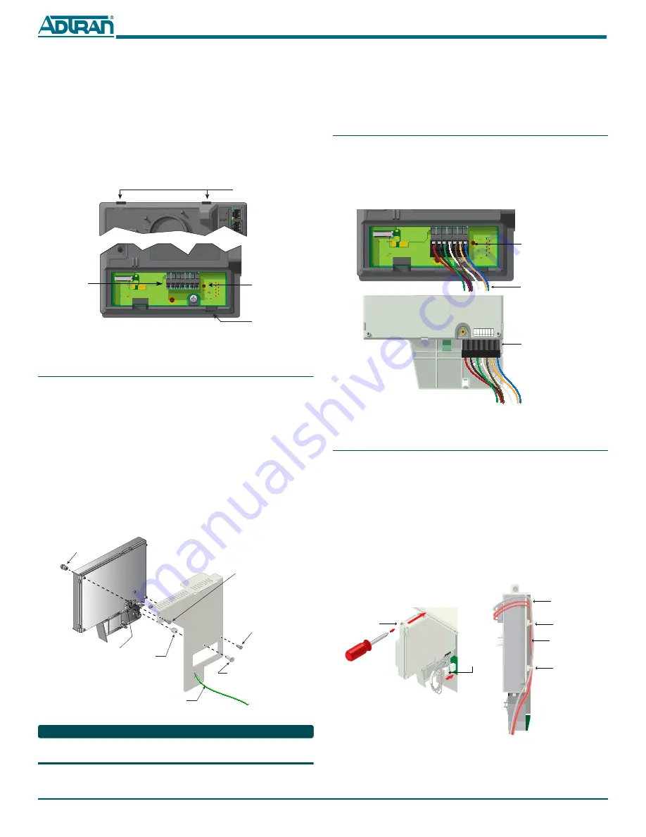
Figure 5. Total Access 374 Mounting Locations
Step 4b: Total Access 352(H) or 362 installation
To install either the Total Access 352(H) or 362 ONT, complete the following
steps:.
1. Attach the 7-Pin Connector (P/N: 3196007PN03-E) to the Cable Assem-
and loosen the screw holding the Support Bracket to
the MDU Housing, and remove the Support Bracket from the MDU
Housing.
and align the Standoff Nut/Screw with the Rear of the
“Teleco Access Only” Connector and the Support Bracket.
4. Attach the Support Bracket to the ONT by inserting a #10-16 Plastite
Screw (P/N 327600205-E) through the upper-left side and lower-right
side of the Support Bracket and into the ONT and tighten. Ensure the
Standoff is still aligned correctly.
Figure 6. Total Access 352 or 362 Mounting Locations
NOTE
, the ground wire is 24” long and is factory installed. You should not
need to remove it to install the ONTs.
Circuit Card
Mounting Point
ONT Bracket
Mounting Points
ONT Circuit Card
Power Connector
Power Connector
Cable Routing Port
Standoff
Nut/Screw
(P/N 3274332-E)
Rear of “Telco
Access Only”
Connector
10-32 x 3/8 Screw
(P/N 327611028-E)
Access Nut
8-18 Plastite Screw
(P/N 327600205-E)
8-18 Plastite Screw
(P/N 327600205-E)
Ground Wire
5. Refer to
and align the ONT and Bracket Mounting Rails with
the guide rails on the MDU housing.
6. If you are going to connect POTS, or Ethernet cables now, refer to
Route Internet Services Cables
. Otherwise, secure the ONT and Support
Bracket to the MDU Housing.
Step 5: Connect Power to the ONTs
To connect power to the ONTs, complete the following steps:
1. Refer to
and connect the PCB end of the Power
Cable from the ONT to the
P2
connector on the
Power Distribution
Block
located at the back of the MDU Housing. Cables should be routed
as illustrated in
. As additional ONTs are installed, connect the
Power Cable to the
P3
,
P4
and
P5
connectors respectively.
Figure 7. Power Connections
Step 6: Route Internet Services Cables
To route the Services Cables, complete the following steps:
1. Refer to
and route the required number of POTS and Ethernet
cables through the Fiber Entry Point located at the base of the MDU
Housing.
2. Refer to
and loosen the screw that holds the Support Bracket
and ONT to the MDU Housing.
3. Connect the POTS and Ethernet cables to the ONT and route as shown
in
and tie wrap as necessary.
4. Refer to
and align the ONT and Bracket Mounting Rails with
the guide rails on the MDU housing.
5. Secure the ONT and Support Bracket to the MDU Housing.
Figure 8. Connecting ONTs
+ 12VDC
12V R
T
N
SIG R
T
N
ON BA
T
REP
BA
T
BA
T
MIS
LOW BA
T
7
6
5
4
3
2
1
Total Access 352(H) and 362
ONT Power Connector
(supplied with ONT)
Back of Electronics Module
Total Access 374 ONT
Power Connector
Cable Assembly
(P/N: 3125P135-E)
Ethernet Drop
(Orange)
POTS Drop
(Gray)
Tie Wrap Anchor
Point
Tie Wrap Anchor
Point
Note: Color of POTS and
Ethernet Drops for clarity
purposes only.
Note: POTS and Ethernet
cables removed for clarity.
Power Cable
“PCB TO ONT”
Phillips Screw and
Support Bracket


