Chapter 2. Installation
2-4
TSU 600 User Manual
61202076L1-1
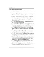
GROUNDING INSTRUCTIONS
The grounding instruction information is from the Underwriters' Labo-
ratory UL 1950, 3rd Edition.
An equipment grounding conductor that is not smaller in size than the
ungrounded branch-circuit supply conductors is to be installed as part
of the circuit that supplies the product or system.
• Bare, covered, or insulated grounding conductors are acceptable.
• Individually covered or insulated equipment grounding conductors
shall have a continuous outer finish that is either green, or green with
one or more yellow stripes.
• The equipment grounding conductor is to be connected to ground at
the service equipment.
• The attachment-plug receptacles in the vicinity of the product or sys-
tem are all to be of a grounding type.
• The equipment grounding conductors serving these receptacles are
to be connected to earth ground at the service equipment.
• A supplementary equipment grounding conductor shall be installed
between the product or system and ground that is in addition to the
equipment grounding conductor in the power-supply cord.
• The supplementary equipment grounding conductor shall not be
smaller in size than the ungrounded branch-circuit supply conduc-
tors.
• The supplementary equipment grounding conductor shall be con-
nected to the product at the terminal provided, and shall be connect-
ed to ground in a manner that will retain the ground connection
when the product is unplugged from the receptacle.
• The connection to ground of the supplementary equipment ground-
ing conductor shall be in compliance with the rules for terminating
bonding jumpers at Part K or Article 250 of the National Electrical
Code, ANSI/NFPA 70.
• Termination of the supplementary equipment grounding conductor
is permitted to be made to building steel, to a metal electrical raceway
system, or to any grounded item that is permanently and reliably
connected to the electrical service equipment ground.
• The supplemental grounding conductor shall be connected to the
equipment using a number 8 ring terminal.
• The terminal should be fastened to the grounding lug provided on
the rear panel of the equipment.
• The ring terminal should be installed using the appropriate crimping
tool (AMP P/N 59250 T-EAD Crimping Tool or equivalent).
Содержание 1202076L1
Страница 18: ...List of Figures vi TSU 600 User Manual 61202076L1 1...
Страница 20: ...List of Tables viii TSU 600 User Manual 61202076L1 1...
Страница 54: ...Chapter 3 Operation 3 14 TSU 600 User Manual 61202076L1 1...
Страница 76: ...Chapter 5 Configuration Menu 5 16 TSU 600 User Manual 61202076L1 1...
Страница 98: ...Chapter 8 Telnet Terminal Menus 8 10 TSU 600 User Manual 61202076L1 1...
Страница 106: ...Appendix B Understanding TR 08 B 4 TSU 600 User Manual 61202076L1 1...
Страница 116: ...Appendix E Specifications E 4 TSU 600 User Manual 61202076L1 1...


