14.4Kbps Modem Option Installation
8
ADP Incorporated
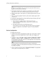
Note
Be aware that each RS-485 device located at the ends of the RS-485 network
must be set for termination and biasing.
5. Install plastic standoffs on the timeclock’s main board to secure the modem
option. (Refer to the earlier 14.4Kbps Modem option figure for reference).
6. Plug the modem option into connector J2 on the main board, and seat it on the
standoffs.
7. Plug one end of the supplied 7-foot telco cable into the modem option’s RJ-11
connector (J1).
8. Feed the telco cable through one of the available openings in the base of the unit.
9. Reconnect power to the timeclock.
a. If the timeclock is equipped with a 12 VDC lead-acid backup
battery, reconnect the backup battery board's cable to connector TB3
on the main board.
b. Reconnect the timeclock to its external power source:
If the timeclock is powered using a DC wall supply, plug the wall supply’s
cable into connector J1 on the #6600177 board, or J3 on the #6600186
board.
Terminal Configuration
To configure the timeclock:
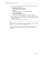
1. At the timeclock, enter Command Mode and then enter command 90. Command
90 allows you to access Program Mode, which is where you configure your
modem.
2. Configure a value for Procedure 9, Step 1: Specify # of Rings Before Modem
Answers. To enable the modem, you must specify a value of between 1 and 4
for this parameter. Specifying a value of 1 for this parameter causes the modem
to auto-answer on the first ring.
Note
When you specify a value other than 0 for Procedure 9, the timeclock
automatically enables a 10 mSec data transmission delay at the timeclock where
the modem is installed.
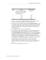
3. Choose a modem-to-modem protocol in Procedure 10, Step 7. The appropriate
values, protocols, and baud rates are as follows:
Содержание 14.4Kbps
Страница 4: ...iv ADP Incorporated ...
Страница 14: ...14 4Kbps Modem Option Installation 14 ADP Incorporated ...


