30
Installation
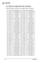
2.13 CN2 pin assignments: Main Connector
CN2 is the major connector for the motion control I/O signals.
No.
Name
I/O
Function (axis / )
No.
Name
I/O
Function (axis / )
1
VPP
O
+5V power supply output
51
VPP
O
+5V power supply output
2
EGND
Ext. power ground
52
EGND
Ext. power ground
3
OUT1+
O
Pulse signal (+),
53
OUT3+
O
Pulse signal (+),
4
OUT1-
O
Pulse signal (-),
54
OUT3-
O
Pulse signal (-),
5
DIR1+
O
Dir. signal (+),
55
DIR3+
O
Dir. signal (+),
6
DIR1-
O
Dir. signal (-),
56
DIR3-
O
Dir. signal (-),
7
SVON1
O
Multi-purpose signal,
57
SVON3
O
Multi-purpose signal,
8
ERC1
O
Dev. ctr, clr. signal,
58
ERC3
O
Dev. ctr, clr. signal,
9
ALM1
I
Alarm signal,
59
ALM3
I
Alarm signal,
10
INP1
I
In-position signal,
60
INP3
I
In-position signal,
11
RDY1
I
Multi-purpose signal,
61
RDY3
I
Multi-purpose signal,
12
EGND
Ext. power ground
62
EGND
Ext. power ground
13
EA1+
I
Encoder A-phase (+),
63
EA3+
I
Encoder A-phase (+),
14
EA1-
I
Encoder A-phase (-),
64
EA3-
I
Encoder A-phase (-),
15
EB1+
I
Encoder B-phase (+),
65
EB3+
I
Encoder B-phase (+),
16
EB1-
I
Encoder B-phase (-),
66
EB3-
I
Encoder B-phase (-),
17
EZ1+
I
Encoder Z-phase (+),
67
EZ3+
I
Encoder Z-phase (+),
18
EZ1-
I
Encoder Z-phase (-),
68
EZ3-
I
Encoder Z-phase (-),
19
VPP
O
+5V power supply output
69
VPP
O
+5V power supply output
20
EGND
Ext. power ground
70
EGND
Ext. power ground
21
OUT2+
O
Pulse signal (+),
71
OUT4+
O
Pulse signal (+),
22
OUT2-
O
Pulse signal (-),
72
OUT4-
O
Pulse signal (-),
23
DIR2+
O
Dir. signal (+),
73
DIR4+
O
Dir. signal (+),
24
DIR2-
O
Dir. signal (-),
74
DIR4-
O
Dir. signal (-),
25
SVON2
O
Multi-purpose signal,
75
SVON4
O
Multi-purpose signal,
26
ERC2
O
Dev. ctr, clr. signal,
76
ERC4
O
Dev. ctr, clr. signal,
27
ALM2
I
Alarm signal,
77
ALM4
I
Alarm signal,
28
INP2
I
In-position signal,
78
INP4
I
In-position signal,
29
RDY2
I
Multi-purpose signal,
79
RDY4
I
Multi-purpose signal,
30
EGND
Ext. power ground
80
EGND
Ext. power ground
31
EA2+
I
Encoder A-phase (+),
81
EA4+
I
Encoder A-phase (+),
32
EA2-
I
Encoder A-phase (-),
82
EA4-
I
Encoder A-phase (-),
33
EB2+
I
Encoder B-phase (+),
83
EB4+
I
Encoder B-phase (+),
34
EB2-
I
Encoder B-phase (-),
84
EB4-
I
Encoder B-phase (-),
35
EZ2+
I
Encoder Z-phase (+),
85
EZ4+
I
Encoder Z-phase (+),
36
EZ2-
I
Encoder Z-phase (-),
86
EZ4-
I
Encoder Z-phase (-),
37
PEL1
I
End limit signal (+),
87
PEL3
I
End limit signal (+),
38
MEL1
I
End limit signal (-),
88
MEL3
I
End limit signal (-),
39
CMP1
O
Position compare output
89
LTC3
I
Position latch input
Содержание MPC-8164
Страница 4: ......
Страница 10: ...vi List of Tables List of Tables Table 2 1 GEME hardware configuration 22 Table 2 2 Base Addresses 22 ...
Страница 12: ......
Страница 14: ...2 Introduction Figure 1 1 PCI 8164 block diagram ...
Страница 50: ...38 Installation ...
Страница 57: ...Signal Connections 45 For more operation information on the encoder feedback signals refer to section 4 4 ...
Страница 70: ...58 Signal Connections ...
Страница 74: ...62 Signal Connections 3 17 1 Isolated input channels 3 17 2 Isolated output channels ...
Страница 75: ...Signal Connections 63 3 17 3 Example of input connection ...
Страница 76: ...64 Signal Connections 3 17 4 Example of output connections ...
Страница 109: ...Operation Theory 97 ...
Страница 110: ...98 Operation Theory ...
Страница 111: ...Operation Theory 99 ...
Страница 112: ...100 Operation Theory ...
Страница 113: ...Operation Theory 101 ...
Страница 148: ...136 Operation Theory Users can use this function to check if auto trigger is running Results ...
Страница 190: ...178 Function Library Return Code ERR_NoError ERR_NoCardFound ERR_PCIBiosNotExist ERR_ConigFileOpenError ...
Страница 193: ...Function Library 181 Src Counter source Return Code ERR_NoError Value Meaning 0 External Feedback 1 Command pulse ...
Страница 280: ...268 Connection Example Figure 7 2 Connection of PCI 8164 with Panasonic Driver ...
Страница 287: ...Connection Example 275 7 3 3 Mechanical Dimensions ...
Страница 296: ...284 Connection Example CNIF and CN2 SJ Refer to 8134 64 series user manual CN1 24V power supply input ...
Страница 297: ...Connection Example 285 7 5 2 Mechanical Dimensions ...
Страница 300: ...288 Connection Example 7 6 Wiring with DIN 814M J3A ...
Страница 304: ...292 Connection Example 7 7 Wiring with DIN 814Y ...
Страница 308: ...296 ...

