Introduction
19
DEX-100
1.6
Left Side I/O Connectors
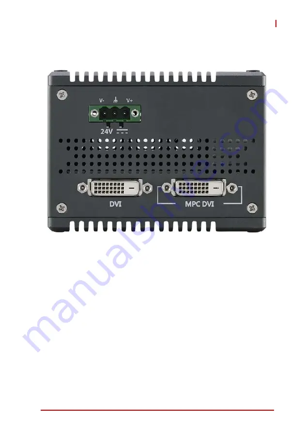
Figure 1-17: Left Side Panel I/O
I/O connectors and controls on the DEX-100 left side panel, as
labeled, are as follows
DC Power Connector
DVI port
MPC DVI port
1.6.1
DC Power Connector
Consists of V+, chassis ground, and V- pins. V+ and V- pins
accept DC power input and chassis ground pin enhances EMC
compatibility. The DC power input accepts 24 VDC input.
Содержание DEX-100
Страница 7: ...Table of Contents vii DEX 100 Getting Service 69...
Страница 8: ...viii Table of Contents Leading EDGE COMPUTING...
Страница 10: ...x List of Tables Leading EDGE COMPUTING This page intentionally left blank...
Страница 12: ...xii List of Figures Leading EDGE COMPUTING This page intentionally left blank...
Страница 18: ...6 Introduction Leading EDGE COMPUTING Figure 1 2 Top View Figure 1 3 Right Side View 140...
Страница 19: ...Introduction 7 DEX 100 Figure 1 4 Left Side View Figure 1 5 Rear Side View...
Страница 34: ...22 Introduction Leading EDGE COMPUTING This page intentionally left blank...
Страница 39: ...Getting Started 27 DEX 100...
Страница 42: ...30 Getting Started Leading EDGE COMPUTING This page intentionally left blank...
Страница 61: ...BIOS Setup 49 DEX 100 A 2 8 Network Stack Configuration Network Stack Enables disables UEFI network stack...
Страница 63: ...BIOS Setup 51 DEX 100 SEMA Features Shows features supported by the SEMA version...
Страница 65: ...BIOS Setup 53 DEX 100 Power Consumption Shows current input current and power as well as system volt ages...
Страница 66: ...54 BIOS Setup Leading EDGE COMPUTING Flags Shows BMC flags with exception codes...
Страница 67: ...BIOS Setup 55 DEX 100 Power Up Lists Power Up Watchdog status...
Страница 68: ...56 BIOS Setup Leading EDGE COMPUTING A 2 10 Miscellaneous OS Selection Allows selection of active OS...
Страница 76: ...64 BIOS Setup Leading EDGE COMPUTING This page intentionally left blank...
Страница 80: ...68 Important Safety Instructions Leading EDGE COMPUTING This page intentionally left blank...


