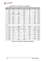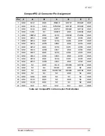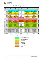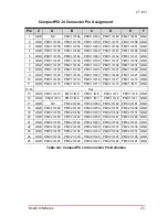
Board Interfaces
15
CT-61
4
Board Interfaces
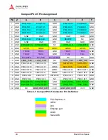
This chapter describes the board layout, connector pin assign-
ments, and jumper settings of the CT-61.
4.1
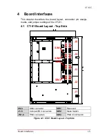
CT-61 Board Layout - Top Side
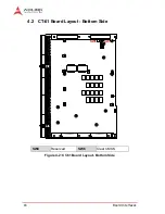
Figure 4-1: CT-61 Board Layout - Top Side
CN8
XMC connector
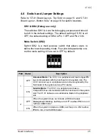
SW1
Reserved
J1-5
CompactPCI connectors
SW2
Mode Switch
JN1-8
PMC connectors
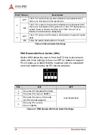
SW3
PMC Clock Switch
233.
2
160
J1
J2
J3
J4
J5
SW1
SW2
JN1 JN3
JN2 JN4
JN5 JN7
JN6 JN8
CN8
SW3
Содержание CT-61
Страница 2: ...Revision History Revision Release Date Description of Change s 1 00 2014 09 25 Initial release ...
Страница 8: ...viii List of Tables This page intentionally left blank ...
Страница 10: ...x List of Figures This page intentionally left blank ...
Страница 20: ...10 Specifications This page intentionally left blank ...
Страница 38: ...28 Board Interfaces This page intentionally left blank ...
Страница 42: ...32 Driver Installation This page intentionally left blank ...
Страница 52: ...42 Utilities This page intentionally left blank ...
Страница 64: ...54 BIOS Setup Utility PC Health Configuration ...
Страница 74: ...64 BIOS Setup Utility This page intentionally left blank ...


