Getting Started
17
AVA-5500
3
Getting Started
Follow the instructions in this chapter to install USIM cards; Wi-Fi,
cellular and M.2 SATA modules; mounting brackets; CFast card;
2.5” SATA drives; ground cable; and DC power supply.
3.1
Removing the Bottom Cover
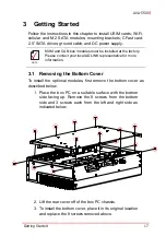
To install the optional modules, first remove the bottom cover as
described below.
1. Place the box PC on a suitable surface with the bottom
side facing up. Remove the 8 screws from the bottom
side and 3 screws each from the left and right side as
indicated below.
2. Lift the rear cover off of the box PC chassis.
3. To install the bottom cover, place it in its original location
and replace the 8 screws removed above.
NOTE:
NOTE:
MXM and CAN bus modules must be installed at the factory.
Please contact your local ADLINK representative for more
information.
Содержание AVA-5500 Series
Страница 8: ...viii Table of Contents Leading EDGE COMPUTING This page intentionally left blank ...
Страница 10: ...x List of Figures Leading EDGE COMPUTING This page intentionally left blank ...
Страница 12: ...xii List of Tables Leading EDGE COMPUTING This page intentionally left blank ...
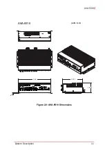
Страница 23: ...System Description 11 AVA 5500 Figure 2 3 AVA 5510 Dimensions 360 225 1 105 4 6 units mm AVA 5510 ...
Страница 76: ...64 BIOS Setup Leading EDGE COMPUTING This page intentionally left blank ...


