background image


pH Amp 


Owner’s Guide


18


Connecting to the PowerLab


Always make sure that the PowerLab is turned off before you connect 
or disconnect the pH Amp. Failure to do this may result in damage to 
the PowerLab, the pH Amp, or both.

Your pH Amp will have been supplied with an I


2


C cable and two 

BNC cables. Use the BNC cables to connect the signal outputs on the 
back of the pH Amp to the signal inputs on the front of the PowerLab. 
If the PowerLab has differential (rather than single-ended) inputs, the 
BNC cables must connect to the positive analog inputs because 
ADInstruments applications will not find the front-end on start-up if a 
negative input is used. Note: you can use the pH Output (electrode 
signal) and the Temperature Output individually – you do not need to 
connect both signal outputs to be able to record data.


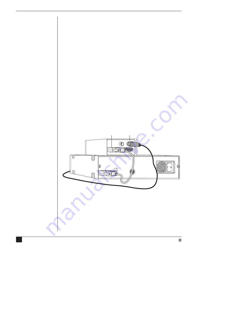
Single Front-end


Connect the I


2


C Output on the back of the PowerLab to the I


2


C Input 

on the back of the pH Amp using the I


2


C cable provided. Figure 2–1 

shows the connections between the pH Amp and the PowerLab.  

Check that all connections are firm. Loose connectors can cause erratic 
front-end behavior, or may cause the front-end to fail to work at all. 
The BNC cable can be tucked under the front-end to keep it out of the 
way, if desired.

Temp Output

pH Output

I

2

C input

Electrode signal output

Figure 2–1

Connecting a pH Amp to a

PowerLab: PowerLabs

have one I

2

C Output, and

each front-end has one I

2

C

Output and one I

2

C Input

Содержание pH Amp

Страница 1: ...pH Amp Owner s Guide ...

Страница 2: ...ments Pty Ltd Other Trademarks Apple Mac and Macintosh are registered trademarks of Apple Computer Inc Windows Windows XP and Windows Vista are either registered trademarks or trademarks of Microsoft Corporation All other trademarks are the property of their respective owners Product ML165 pH Amp Document Number U ML165 OG 002B Part Number 4611 Copyright February 2008 ADInstruments Pty Ltd Unit 13...

Страница 3: ...ators 16 The Temperature Input 16 The Back Panel 16 The Signal Outputs 16 I2 C Connector 16 2 Setting Up 17 Connecting to the PowerLab 18 Single Front end 18 Multiple Front ends 19 Using ADInstruments Programs 19 The Front end Driver 20 Front end Self test 20 Software Behavior 20 The pH Amp 21 Signal Display 22 Setting the Range 22 Filtering 23 Inverting the Signal 23 Units 23 Calibrating the pH A...

Страница 4: ...24 Setting the Range 26 Inverting the Signal 26 Units 26 The Temperature Probe 26 ATechnical Aspects 27 pH Amp Operation 27 Technical Description 28 B Troubleshooting 29 C Specifications 31 pH Section 31 Temperature Section 31 Control Port 32 Physical Configuration 32 Index 33 ...

Страница 5: ...gnose treat or monitor a subject Furthermore no product is intended for the prevention curing or alleviation of disease injury or handicap Where a product meets IEC 60601 1 it is under the principle that it is a more rigorous standard than other standards that could be chosen and it provides a high safety level for subjects and operators The choice to meet IEC 60601 1 is in no way to be interprete...

Страница 6: ...ected symbol This means that the input connectors are suitable for connection to human subjects even when there is direct electrical connection to the heart Warning symbol The exclamation mark inside a triangle means that the supplied documentation must be consulted for operating cautionary or safety information before using the device Further information is available on request Bio Amp Safety Ins...

Страница 7: ... in isolated stimulator are electrically isolated However they can produce pulses of up to 100 V at up to 20 mA Injury can still occur from careless use of these devices Several points must be observed for safe operation of the Isolated Stimulator The Isolated Stimulator output must only be used with the supplied bar stimulus electrode The Isolated Stimulator output must not be used with individua...

Страница 8: ...ftware or by flicking down the safety switch on the front panel of any built in Isolated Stimulator or the ML180 Stimulus Isolator The ML180 Stimulus Isolator is supplied with a special transformer plug pack The plug pack complies with medical safety requirements Therefore under no circumstances should any other transformer be used with the Stimulus Isolator For a replacement transformer plug pack ...

Страница 9: ...ment that are marked as an APPLIED PART to the subject APPLIED PARTS may be recognized by the BF or CF symbols which appear in the Safety Symbols section of these Safety Notes Only CF rated APPLIED PARTS must be used for direct cardiac connection Never connect parts which are marked as an APPLIED PART to those which are not marked as APPLIED PARTS Do not touch the subject to which the PowerLab or ...

Страница 10: ...outlets are used they are subject to the following constraints They shall not be placed on the floor Additional multiple portable socket outlets or extension cords shall not be connected to the system They shall only be used for supplying power to equipment which is intended to form part of the system Cleaning and Sterilization ADInstruments products may be wiped down with a lint free cloth moisten...

Страница 11: ...ts If the PowerLab system is found not to comply with such testing you should contact your PowerLab representative to arrange for the equipment to be checked and serviced Do not attempt to service the device yourself Environment Electronic components are susceptible to corrosive substances and atmospheres and must be kept away from laboratory chemicals Storage Conditions Temperature in the range 0...

Страница 12: ...pH Amp Owner s Guide 12 ...

Страница 13: ...lectrodes potentiometric ion selective electrodes ISEs redox or ORP oxidation reduction potentiometric electrodes other high impedance sources up to 2 V requiring electrometer input The built in temperature amplifier can be used to provide automatic temperature compensation ATC for pH and ion selective electrodes This chapter provides an overview of the pH Amp and describes its features 1 Overview ...

Страница 14: ... ADInstruments Front ends The PowerLab system consists of a recording unit and application programs on the computer to which the unit is connected It is an integrated system of hardware and software designed to record display and analyze experimental data Your pH Amp is one of a family of front ends meant for use with your PowerLab system Front ends are ancillary devices that extend the system s c...

Страница 15: ...ull software control It is automatically recognized by ADInstruments software which controls the gain range signal filtering and other settings The Front Panel The Electrode and Reference Input The BNC input connector of the pH Amp provides connection for a pH ISE or redox electrode Combination electrodes that is those with an internal reference will only need to be connected to this input Electrod...

Страница 16: ...t provides the signal of the temperature at the temperature probe The two signals are independent and do not have to be recorded simultaneously I2 C Sockets Two nine pin sockets are used to communicate with the PowerLab they are marked I2 C Bus a bus is simply information transmission circuitry such as cable and connectors The Input socket connects to the PowerLab or the output of a previous ADIns...

Страница 17: ...how to connect the pH Amp to your PowerLab and perform a quick test to make sure that it is working properly The best way to configure your system for one or more front ends is discussed along with how to use the front end with ADInstruments application programs ...

Страница 18: ...up if a negative input is used Note you can use the pH Output electrode signal and the Temperature Output individually you do not need to connect both signal outputs to be able to record data Single Front end Connect the I2 C Output on the back of the PowerLab to the I2 C Input on the back of the pH Amp using the I2 C cable provided Figure 2 1 shows the connections between the pH Amp and the Power...

Страница 19: ...pe The combined amplification and filtering of the pH Amp the PowerLab and the program are presented as a single set of software controls replacing the Input Amplifier dialog with the pH Amp dialog The LabChart Help Center and Scope User s Guide describe the Input Amplifier and Stimulator dialogs and explain some of the terms and concepts used here The documentation for LabChart and Scope does not cov...

Страница 20: ...itialization you should see the PowerLab and pH Amp Status indicators flash briefly and then remain lit Note if only the pH Output is connected then the indicator for the Temperature probe will not light and vice versa If the indicators do not light check the connections and repeat the procedure If this does not solve the problem contact your ADInstruments representative Software Behavior When the p...

Страница 21: ...ht or left arrow keys on the keyboard to move to the equivalent dialogs for adjacent channels This skips channels that are turned off The channel number is shown next to the arrows Amplitudeaxis PauseandScrollbuttons Rangepop up menu ClickthisbuttontoopentheUnitsConversiondialog Signalamplitude Low passfilter pop upmenu Pause Scrollbutton Amplitudeaxis Signalamplitude Compression buttons Low passf...

Страница 22: ...he Amplitude axis of the Chart Window controls are identical and any change is applied to the Chart Window Setting the Range The Range pop up menu lets you select the input range or sensitivity of the channel the combined range of the pH Amp and PowerLab Changing the range in the pH Amp dialog is the equivalent to changing it in the Chart or Scope window applied once you click OK At 25 C a range o...

Страница 23: ...t Help Center Calibrating the pH Amp Electrode Calibration of the pH electrode should be performed using the pH Extension The pH Extension is a LabChart software plug in that performs single or double point calibration of the pH or ion selective electrode prepares a calibration graph from the measured electrode signal enables manual temperature compensation MTC adjustment or enables automatic temp...

Страница 24: ...annel number is shown next to the arrows The Temperature dialogs for LabChart are shown in Figure 2 6 and Figure 2 7 The dialogs and controls for Scope are similar Signal Display The input signal is displayed so that you can see the effect of changing the settings no data are actually recorded when setting up the Temperature Amp The average signal value is displayed at the top of the display area ...

Страница 25: ...dragging it in various ways to make the best use of the available display area It functions the same as the Amplitude axis of the Chart Window controls are identical and any change is applied to the Chart Window Pause Scrollbutton Clickthistoopenthe UnitsConversiondialog Thefactory settingsforthe RTDprobeare 0V 0 C 5V 100 C Unitpop up menu Amplitudeaxis Signalamplitude Rangepop upmenu Compressionb...

Страница 26: ...V C If temperature accuracy is of critical importance you should use two precision temperature sources to calibrate the temperature probe more accurately Note when using the pH Extension with automatic temperature compensation the Temperature signal must first be calibrated in degrees Celsius C degrees Fahrenheit F or Kelvin K This units conversion only applies to subsequently recorded signals so i...

Страница 27: ...pment voids your rights under warranty pH Amp Operation The pH Amp and other ADInstruments front ends have been designed to be used with a PowerLab system The pH Amp is an extension of the PowerLab s analog inputs It provides a very high impedance amplifier suitable for direct connection to pH or other ion selective electrodes software controlled filtering for the pH channel reference electrode inpu...

Страница 28: ...ng a reference electrode to the analog ground of the amplifier The input amplifier gain can be set by the software to 1 or 10 depending on the required sensitivity The output of the electrometer amplifier is fed to a 2 pole 10 Hz low pass filter which is software selectable The output is then fed to the PowerLab for further amplification and filtering The temperature amplifier is effectively a separate A...

Страница 29: ...fixed by ensuring that the connecting cables are correctly connected and firmly attached and then re starting the LabChart or Scope software If the solutions here do not work earlier chapters the LabChart Help Center and the guide to your PowerLab may contain possible solutions If none of the solutions here or elsewhere are of help then consult your ADInstruments representative B Troubleshooting ...

Страница 30: ...ab Either or both online indicators fail to light when the application is opened and the pH Amp is not accessible from LabChart or Scope The I2 C cable from the pH Amp to the PowerLab may not be properly connected Check to see that the I2 C cables are firmly seated and screwed in Try new cables to check that the BNC and or I2 C cables are working correctly If you have tried the above suggestions an...

Страница 31: ...s 0 0015 of range Input impedance 1013 Ω typical Amplifier noise 1μV rms 4 μV p p with a bandwidth of DC 10 Hz Maximum Input 10 V Input connection type Insulated BNC Low pass filter 10 Hz 3 dB frequency Low pass filter accuracy 3 0 Low pass filter type Bessel 2 pole Temperature Section Temperature probe type RTD 100 Ω type supplied with unit Temperature range 100 C Temperature accuracy 0 2 C C Specifi...

Страница 32: ...nection 3 pin mini audio jack Control Port I2 C input and output Male and female DB 9 pin connectors Provides control and power Power requirements 17 V DC 8 V DC 3 W Physical Configuration Dimensions h w d 50 mm 76 mm 260 mm 1 97 3 0 10 2 Weight 0 8 kg 1 8 lb Operating conditions 5 35 C 0 90 humidity non condensing ADInstruments reserves the right to alter these specifications at any time ...

Страница 33: ... panel 15 front end driver 20 front ends general 14 15 I I2C bus 14 16 L LabChart 19 M maintenance 10 P pH Amp filtering 23 setting the range sensitivity 22 setup 21 26 software 21 23 pH calibration extension 23 pH electrode calibration 23 pH range settings 22 PowerLab system 14 problems and solutions 29 30 R Reference connector 15 S Safety Notes 5 11 Scope 19 self test 20 single ended inputs 18 so...

Страница 34: ...al specifications 31 32 temperature probe calibration 26 temperature signal setting the range sensitivity 26 setup 24 26 Units Conversion 26 troubleshooting 29 30 U user modification voids warranty 27 using ADInstruments programs 19 26 ...

Отзывы: