pH Amp
Owner’s Guide
16
The Online Indicators
When lit, these indicate that the software (such as LabChart or Scope)
has located and initialized the pH Amp. If the software is on and an
indicator has not lit up, check that the pH Amp is properly connected.
There are two indicators, one to show connection of the electrode
signal, and the other to show connection of the temperature signal.
The Temperature Input
The temperature input can be used with the 100
Ω
platinum resistance
(RTD) probe supplied with the unit.
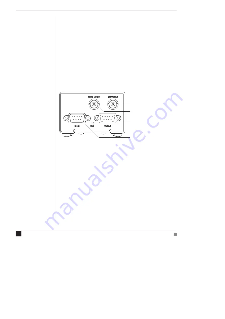
The Back Panel
The Signal Outputs
The pH Output BNC socket provides the signal of the potential at the
electrode, while the Temp Output BNC socket provides the signal of
the temperature at the temperature probe. The two signals are
independent and do
not
have to be recorded simultaneously.
I
2
C Sockets
Two nine-pin sockets are used to communicate with the PowerLab
(they are marked ‘I
2
C Bus’: a ‘bus’ is simply information-transmission
circuitry such as cable and connectors). The Input socket connects to
the PowerLab (or the output of a previous ADInstruments front-end).
This connection provides power and various control signals (such as
gain range and filter selection) to the pH Amp from the PowerLab.
The Output socket connects further front-ends to the system, in series,
output to input (this is discussed in more detail in the next chapter).
pH signal, BNC socket
Temperature signal, BNC socket
I
2
C connection to a further
front-end
I
2
C connection from the
PowerLab or previous front-end
Figure 1–2
The pH Amp back panel
Содержание pH Amp
Страница 1: ...pH Amp Owner s Guide ...
Страница 12: ...pH Amp Owner s Guide 12 ...


